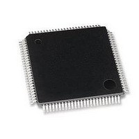
LAN9118-MD SMSC, LAN9118-MD Datasheet - Page 40

LAN9118-MD
Manufacturer Part Number
LAN9118-MD
Description
Ethernet ICs HiPerfrm Sngl-Chip 10/100 Ethrnt
Manufacturer
SMSC
Type
Single Chip MAC and PHYr
Datasheet
1.LAN9118-MT.pdf
(132 pages)
Specifications of LAN9118-MD
Ethernet Connection Type
10 Base-T, 100 Base-TX
Minimum Operating Temperature
0 C
Mounting Style
SMD/SMT
Product
Ethernet Controllers
Number Of Transceivers
1
Standard Supported
802.3
Data Rate
10 MB, 100 MB
Supply Voltage (max)
3.3 V
Supply Voltage (min)
0 V
Maximum Operating Temperature
+ 70 C
Package / Case
TQFP-100
Lead Free Status / RoHS Status
Lead free / RoHS Compliant
- Current page: 40 of 132
- Download datasheet (2Mb)
Revision 1.5 (07-11-08)
3.10.2.3
3.10.3
3.10.3.1
Denotes a level-triggered "sticky" status bit
PME_TYPE
PME_POL
PME_IND
PME_EN
phy_int
WUEN
WUFR
MPEN
MPR
Power Managment Event Indicators
Figure 3.11
pme_interrupt signals. The pme_interrupt signal is used to set the PME_INT status bit in the INT_STS
register, which, if enabled, will generate a host interrupt upon detection of a power management event.
The PME_INT status bit in INT_STS will remain set until the internal pme_interrupt signal is cleared
by clearing the WUPS bits, or by clearing the corresponding WOL_EN or ED_EN bit. After clearing the
internal pme_interrupt signal, the PME_INT status bit may be cleared by writing a ‘1’ to this bit in the
INT_STS register. It should be noted that the LAN9118 can generate a host interrupt regardless of the
state of the PME_EN bit, or the external PME signal.
The external PME signal can be setup for pulsed, or static operation. When the PME_IND bit in the
PMT_CTRL register is set to a ‘1’, the external PME signal will be driven active for 50ms upon
detection of a wake-up event. When the PME_IND bit is cleared, the PME signal will be driven
continously upon detection of a wake-up event. The PME signal is deactivated by clearing the WUPS
bits, or by clearing the corresponding WOL_EN or ED_EN bit. The PME signal can also be deactivated
by clearing the PME_EN bit.
Internal PHY Power-Down Modes
There are 2 power-down modes for the internal Phy:
General Power-Down
This power-down is controlled by register 0, bit 11. In this mode the internal PHY, except the
management interface, is powered-down and stays in that condition as long as Phy register bit 0.11 is
HIGH. When bit 0.11 is cleared, the PHY powers up and is automatically reset. Please refer to
5.5.1, "Basic Control Register," on page 105
is a simplified block diagram of the logic that controls the external PME, and internal
Figure 3.11 PME and PME_INT Signal Generation
WOL_EN
ED_EN
WUPS
WUPS
DATASHEET
50ms
40
PME_INT_EN
High Performance Single-Chip 10/100 Non-PCI Ethernet Controller
for additional information on this register.
PME_INT
Other System
Interrupts
LOGIC
IRQ_EN
PME
SMSC LAN9118
Datasheet
Section
IRQ
Related parts for LAN9118-MD
Image
Part Number
Description
Manufacturer
Datasheet
Request
R

Part Number:
Description:
IC ETHERNET CTRLR 10/100 100TQFP
Manufacturer:
SMSC
Datasheet:

Part Number:
Description:
MCU, MPU & DSP Development Tools Evaluation Board
Manufacturer:
SMSC

Part Number:
Description:
MCU, MPU & DSP Development Tools Evaluation Board
Manufacturer:
SMSC

Part Number:
Description:
FAST ETHERNET PHYSICAL LAYER DEVICE
Manufacturer:
SMSC Corporation
Datasheet:

Part Number:
Description:
357-036-542-201 CARDEDGE 36POS DL .156 BLK LOPRO
Manufacturer:
SMSC Corporation
Datasheet:

Part Number:
Description:
357-036-542-201 CARDEDGE 36POS DL .156 BLK LOPRO
Manufacturer:
SMSC Corporation
Datasheet:

Part Number:
Description:
357-036-542-201 CARDEDGE 36POS DL .156 BLK LOPRO
Manufacturer:
SMSC Corporation
Datasheet:

Part Number:
Description:
4-PORT USB2.0 HUB CONTROLLER
Manufacturer:
SMSC Corporation
Datasheet:

Part Number:
Description:
Manufacturer:
SMSC Corporation
Datasheet:

Part Number:
Description:
Manufacturer:
SMSC Corporation
Datasheet:

Part Number:
Description:
FDC37C672ENHANCED SUPER I/O CONTROLLER WITH FAST IR
Manufacturer:
SMSC Corporation
Datasheet:

Part Number:
Description:
COM90C66LJPARCNET Controller/Transceiver with AT Interface and On-Chip RAM
Manufacturer:
SMSC Corporation
Datasheet:

Part Number:
Description:
Manufacturer:
SMSC Corporation
Datasheet:

Part Number:
Description:
Manufacturer:
SMSC Corporation
Datasheet:


