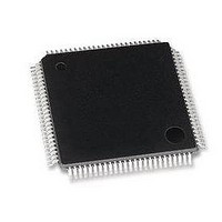
LAN9118-MD SMSC, LAN9118-MD Datasheet - Page 63

LAN9118-MD
Manufacturer Part Number
LAN9118-MD
Description
Ethernet ICs HiPerfrm Sngl-Chip 10/100 Ethrnt
Manufacturer
SMSC
Type
Single Chip MAC and PHYr
Datasheet
1.LAN9118-MT.pdf
(132 pages)
Specifications of LAN9118-MD
Ethernet Connection Type
10 Base-T, 100 Base-TX
Minimum Operating Temperature
0 C
Mounting Style
SMD/SMT
Product
Ethernet Controllers
Number Of Transceivers
1
Standard Supported
802.3
Data Rate
10 MB, 100 MB
Supply Voltage (max)
3.3 V
Supply Voltage (min)
0 V
Maximum Operating Temperature
+ 70 C
Package / Case
TQFP-100
Lead Free Status / RoHS Status
Lead free / RoHS Compliant
High Performance Single-Chip 10/100 Non-PCI Ethernet Controller
Datasheet
SMSC LAN9118
Once auto-negotiation has completed, information about the resolved link can be passed back to the
controller via the internal Serial Management Interface (SMI). The results of the negotiation process
are reflected in the Speed Indication bits in register 31, as well as the Link Partner Ability Register
(Register 5).
The auto-negotiation protocol is a purely physical layer activity and proceeds independently of the MAC
controller.
The advertised capabilities of the PHY are stored in register 4 of the SMI registers. The default
advertised by the PHY is determined by user-defined on-chip signal options.
The following blocks are activated during an Auto-negotiation session:
When enabled, auto-negotiation is started by the occurrence of one of the following events:
On detection of one of these events, the PHY begins auto-negotiation by transmitting bursts of Fast
Link Pulses (FLP). These are bursts of link pulses from the 10M transmitter. They are shaped as
Normal Link Pulses and can pass uncorrupted down CAT-3 or CAT-5 cable. A Fast Link Pulse Burst
consists of up to 33 pulses. The 17 odd-numbered pulses, which are always present, frame the FLP
burst. The 16 even-numbered pulses, which may be present or absent, contain the data word being
transmitted. Presence of a data pulse represents a “1”, while absence represents a “0”.
The data transmitted by an FLP burst is known as a “Link Code Word.” These are defined fully in IEEE
802.3 clause 28. In summary, the PHY advertises 802.3 compliance in its selector field (the first 5 bits
of the Link Code Word). It advertises its technology ability according to the bits set in register 4 of the
SMI registers.
There are 4 possible matches of the technology abilities. In the order of priority these are:
If the full capabilities of the PHY are advertised (100M, full-duplex), and if the link partner is capable
of 10M and 100M, then auto-negotiation selects 100M as the highest performance mode. If the link
partner is capable of half and full-duplex modes, then auto-negotiation selects full-duplex as the highest
performance operation.
Once a capability match has been determined, the link code words are repeated with the acknowledge
bit set. Any difference in the main content of the link code words at this time will cause auto-negotiation
to re-start. Auto-negotiation will also re-start if not all of the required FLP bursts are received.
Writing register 4 bits [8:5] allows software control of the capabilities advertised by the PHY. Writing
register 4 does not automatically re-start auto-negotiation. Register 0, bit 9 must be set before the new
Auto-negotiation (digital)
100M ADC (analog)
100M PLL (analog)
100M equalizer/BLW/clock recovery (DSP)
10M SQUELCH (analog)
10M PLL (analog)
10M Transmitter (analog)
Hardware reset
Software reset
Power-down reset
Link status down
Setting register 0, bit 9 high (auto-negotiation restart)
100M full-duplex (Highest priority)
100M half-duplex
10M full-duplex
10M half-duplex
DATASHEET
63
Revision 1.5 (07-11-08)


