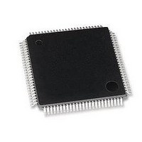
LAN9118-MD SMSC, LAN9118-MD Datasheet - Page 96

LAN9118-MD
Manufacturer Part Number
LAN9118-MD
Description
Ethernet ICs HiPerfrm Sngl-Chip 10/100 Ethrnt
Manufacturer
SMSC
Type
Single Chip MAC and PHYr
Datasheet
1.LAN9118-MT.pdf
(132 pages)
Specifications of LAN9118-MD
Ethernet Connection Type
10 Base-T, 100 Base-TX
Minimum Operating Temperature
0 C
Mounting Style
SMD/SMT
Product
Ethernet Controllers
Number Of Transceivers
1
Standard Supported
802.3
Data Rate
10 MB, 100 MB
Supply Voltage (max)
3.3 V
Supply Voltage (min)
0 V
Maximum Operating Temperature
+ 70 C
Package / Case
TQFP-100
Lead Free Status / RoHS Status
Lead free / RoHS Compliant
Revision 1.5 (07-11-08)
BITS
7-6
13
12
11
10
9
8
Hash/Perfect Filtering Mode (HPFILT). When reset (0), the LAN9118 will implement a perfect
address filter on incoming frames according the address specified in the MAC address register.
When set (1), the address check Function does imperfect address filtering of multicast incoming
frames according to the hash table specified in the multicast hash table register.
If the Hash Only Filtering mode (HO) bit is set (1), then the physical (IA) are imperfect filtered too. If
the Hash Only Filtering mode (HO) bit is reset (0), then the IA addresses are perfect address filtered
according to the MAC Address register
Late Collision Control (LCOLL). When set, enables retransmission of the collided frame even after
the collision period (late collision). When reset, the MAC disables frame transmission on a late
collision. In any case, the Late Collision status is appropriately updated in the Transmit Packet status.
Disable Broadcast Frames (BCAST). When set, disables the reception of broadcast frames. When
reset, forwards all broadcast frames to the application.
Note:
Disable Retry (DISRTY). When set, the MAC attempts only one transmission. When a collision is
seen on the bus, the MAC ignores the current frame and goes to the next frame and a retry error is
reported in the Transmit status. When reset, the MAC attempts 16 transmissions before signaling a
retry error.
Reserved
Automatic Pad Stripping (PADSTR). When set, the MAC strips the pad field on all incoming frames,
if the length field is less than 46 bytes. The FCS field is also stripped, since it is computed at the
transmitting station based on the data and pad field characters, and is invalid for a received frame
that has had the pad characters stripped. Receive frames with a 46-byte or greater length field are
passed to the Application unmodified (FCS is not stripped). When reset, the MAC passes all incoming
frames to the host unmodified.
BackOff Limit (BOLMT). The BOLMT bits allow the user to set its back-off limit in a relaxed or
aggressive mode. According to IEEE 802.3, the MAC has to wait for a random number [r] of slot-
times** after it detects a collision, where:
(eq.1)0 < r <
The exponent K is dependent on how many times the current frame to be transmitted has been retried,
as follows:
(eq.2)K = min (n, 10) where n is the current number of retries.
If a frame has been retried three times, then K = 3 and r= 8 slot-times maximum. If it has been retried
12 times, then K = 10, and r = 1024 slot-times maximum.
An LFSR (linear feedback shift register) 20-bit counter emulates a 20bit random number generator,
from which r is obtained. Once a collision is detected, the number of the current retry of the current
frame is used to obtain K (eq.2). This value of K translates into the number of bits to use from the
LFSR counter. If the value of K is 3, the MAC takes the value in the first three bits of the LFSR counter
and uses it to count down to zero on every slot-time. This effectively causes the MAC to wait eight
slot-times. To give the user more flexibility, the BOLMT value forces the number of bits to be used
from the LFSR counter to a predetermined value as in the table below.
Thus, if the value of K = 10, the MAC will look at the BOLMT if it is 00, then use the lower ten bits of the LFSR
counter for the wait countdown. If the BOLMT is 10, then it will only use the value in the first four bits for the
wait countdown, etc.
**Slot-time = 512 bit times. (See IEEE 802.3 Spec., Secs. 4.2.3.25 and 4.4.2.1)
When wake-up frame detection is enabled via the WUEN bit of the
Control and Status
state of this bit.
2
K
Register, a broadcast wake-up frame will wake-up the device despite the
BOLMT Value
2’b00
2’b01
2’b10
2’b11
DATASHEET
DESCRIPTION
96
High Performance Single-Chip 10/100 Non-PCI Ethernet Controller
# Bits Used from LFSR Counter
10
8
4
1
WUCSR—Wake-up
SMSC LAN9118
Datasheet


