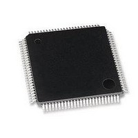
LAN9118-MD SMSC, LAN9118-MD Datasheet - Page 38

LAN9118-MD
Manufacturer Part Number
LAN9118-MD
Description
Ethernet ICs HiPerfrm Sngl-Chip 10/100 Ethrnt
Manufacturer
SMSC
Type
Single Chip MAC and PHYr
Datasheet
1.LAN9118-MT.pdf
(132 pages)
Specifications of LAN9118-MD
Ethernet Connection Type
10 Base-T, 100 Base-TX
Minimum Operating Temperature
0 C
Mounting Style
SMD/SMT
Product
Ethernet Controllers
Number Of Transceivers
1
Standard Supported
802.3
Data Rate
10 MB, 100 MB
Supply Voltage (max)
3.3 V
Supply Voltage (min)
0 V
Maximum Operating Temperature
+ 70 C
Package / Case
TQFP-100
Lead Free Status / RoHS Status
Lead free / RoHS Compliant
Revision 1.5 (07-11-08)
3.10
3.10.1
3.10.2
3.10.2.1
LAN9118 supports power-down modes to allow applications to minimize power consumption. The
following sections describe these modes.
System Description
Power is reduced to various modules by disabling the clocks as outlined in Table 3.9, “Power
Management States,” on page 39. All configuration data is saved when in either of the two low power
states. Register contents are not affected unless specifically indicated in the register description.
Functional Description
There is one normal operating power state, D0 and there are two power saving states: D1, and D2.
Upon entry into either of the two power saving states, only the PMT_CTRL register is accessible for
read operations. In either of the power saving states the READY bit in the PMT_CTRL register will be
cleared. Reads of any other addresses are forbidden until the READY bit is set. All writes, with the
exception of the wakeup write to BYTE_TEST, are also forbidden until the READY bit is set. Only when
in the D0 (Normal) state, when the READY bit is set, can the rest of the device be accessed.
Note 3.4
In system configurations where the PME signal is shared amongst multiple devices, the WUPS field
within the PMT_CTRL register can be read to determine which LAN9118 device is driving the PME
signal.
When the LAN9118 is in a power saving state (D1 or D2), a write cycle to the BYTE_TEST register
will return the LAN9118 to the D0 state.
and
consumption values for each power state.
Note 3.5
D1 Sleep
Power consumption is reduced in this state by disabling clocks to portions of the internal logic as
shown in
operational. This state is entered when the host writes a '01' to the PM_MODE bits in the Power
Management (PMT_CTRL) register. The READY bit in PMT_CTRL is cleared when entering the D1
state.
Wake-up frame and Magic Packet detection are automatically enabled in the D1 state. If properly
enabled via the WOL_EN and PME_EN bits, the LAN9118 will assert the PME hardware signal upon
the detection of the wake-up frame or magic packet. The LAN9118 can also assert the host interrupt
(IRQ) on detection of a wake-up frame or magic packet. Upon detection, the WUPS field in PMT_CTRL
will be set to a 10b.
Note 3.6
Note 3.7
A write to the BYTE_TEST register, regardless of whether a wake-up frame or Magic Packet was
detected, will return LAN9118 to the D0 state and will reset the PM_MODE field to the D0 state. As
noted above, the host is required to check the READY bit and verify that it is set before attempting
any other reads or writes of the device.
Power Management
Table 7.2, “Power Consumption Device and System Components,” on page
Table
The LAN9118 must always be read at least once after power-up, reset, or upon return from
a power-saving state, otherwise write operations will not function.
When the LAN9118 is in a power saving state, a write of any data to the BYTE_TEST
register will wake-up the device. DO NOT PERFORM WRITES TO OTHER
ADDRRESSES while the READY bit in the PMT_CTRL register is cleared.
The PME interrupt status bit (PME_INT) in the INT_STS register is set regardless of the
setting of PME_EN.
Wake-up frame and Magic Packet detection is automatically enabled when entering the D1
state. For wake-up frame detection, the wake-up frame filter must be programmed before
entering the D1 state (see
the host interrupt and PME signal must be enabled prior to entering the D1 state.
3.9. In this mode the clock to the internal PHY and portions of the MAC are still
DATASHEET
Section 3.5, "Wake-up Frame Detection," on page
Table 7.1, “Power Consumption Device Only,” on page 126
38
High Performance Single-Chip 10/100 Non-PCI Ethernet Controller
127, shows the power
SMSC LAN9118
27). If used,
Datasheet


