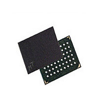
MT48H32M16LFBF-75 IT:B Micron Technology Inc, MT48H32M16LFBF-75 IT:B Datasheet - Page 21

MT48H32M16LFBF-75 IT:B
Manufacturer Part Number
MT48H32M16LFBF-75 IT:B
Description
Manufacturer
Micron Technology Inc
Type
SDRAMr
Datasheet
1.MT48H32M16LFBF-75_ITB.pdf
(86 pages)
Specifications of MT48H32M16LFBF-75 IT:B
Organization
32Mx16
Density
512Mb
Address Bus
15b
Access Time (max)
8/5.4ns
Maximum Clock Rate
133MHz
Operating Supply Voltage (typ)
1.8V
Package Type
VFBGA
Operating Temp Range
-40C to 85C
Operating Supply Voltage (max)
1.95V
Operating Supply Voltage (min)
1.7V
Supply Current
90mA
Pin Count
54
Mounting
Surface Mount
Operating Temperature Classification
Industrial
Lead Free Status / Rohs Status
Compliant
Table 11: AC Functional Characteristics
Notes 1–5 apply to all parameters and conditions
PDF: 09005aef82ea3742
512mb_mobile_sdram_y47m.pdf – Rev. H 12/09 EN
Parameter
Last data-in to burst STOP command
READ/WRITE command to READ/WRITE command
Last data-in to new READ/WRITE command
CKE to clock disable or power-down entry mode
Data-in to ACTIVE command
Data-in to PRECHARGE command
DQM to input data delay
DQM to data mask during WRITEs
DQM to data High-Z during READs
WRITE command to input data delay
LOAD MODE REGISTER command to ACTIVE or REFRESH command
CKE to clock enable or power-down exit mode
Last data-in to PRECHARGE command
Data-out High-Z from PRECHARGE command
Notes:
1. A full initialization sequence is required before proper device operation is ensured.
2. The minimum specifications are used only to indicate cycle time at which proper opera-
3. In addition to meeting the transition rate specification, the clock and CKE must transit
4.
5. AC timing tests have V
6. The clock frequency must remain constant (stable clock is defined as a signal cycling with-
7.
8. This device requires 8192 AUTO REFRESH cycles every 64ms (
9. AC characteristics assume
tion over the full temperature range (0˚C ≤ T
≤ T
between V
Outputs measured for 1.8V at 0.9V with equivalent load:
Test loads with full DQ driver strength. Performance will vary with actual system DQ bus
capacitive loading, termination, and programmed drive strength.
input transition time is longer than
V
in timing constraints specified for the clock ball) during access or precharge states
(READ, WRITE, including
the data rate.
t
reference to V
uted AUTO REFRESH command every 7.8125μs meets the refresh requirement and en-
sures that each row is refreshed. Alternatively, 8192 AUTO REFRESH commands can be
issued in a burst at the minimum cycle rate (
timing must be derated. Input setup times require an additional 50ps for each 100 mV/
HZ defines the time at which the output achieves the open circuit condition, it is not a
IH,min
A
≤ +85˚C industrial temperature) is ensured.
and no longer at the V
IH
and V
Electrical Specifications – AC Operating Conditions
OH
512Mb: 32 Meg x 16, 16 Meg x 32 Mobile SDRAM
or V
IL
(or between V
OL
IL
. The last valid data element will meet
and V
t
WR, and PRECHARGE commands). CKE may be used to reduce
21
t
T = 1ns. For command and address input slew rates <0.5V/ns,
CL = 3
CL = 2
IH/2
IH
with timing referenced to V
crossover point.
IL
t
Micron Technology, Inc. reserves the right to change products or specifications without notice.
Tmax, then the timing is referenced at V
and V
Symbol
t
t
t
t
t
t
CKED
t
t
t
t
t
DQM
DWD
t
t
t
DQD
MRD
DQZ
ROH
CCD
DAL
BDL
CDL
PED
RDL
DPL
IH
t
) in a monotonic manner.
A
RFC), once every 64ms.
≤ +70˚C standard temperature and –40˚C
-6
1
1
1
1
5
2
0
0
2
0
2
1
2
3
2
Q
t
IH/2
© 2007 Micron Technology, Inc. All rights reserved.
REF). Providing a distrib-
-75
t
OH before going High-Z.
1
1
1
1
5
2
0
0
2
0
2
1
2
3
2
= crossover point. If the
Units
t
t
t
t
t
t
t
t
t
t
t
t
t
t
t
CK
CK
CK
CK
CK
CK
CK
CK
CK
CK
CK
CK
CK
CK
CK
20pF
IL,max
Notes
14, 16
15, 16
15, 16
and
12
12
13
13
12
12
12
12
13
12


