EP3C25U256I7 Altera, EP3C25U256I7 Datasheet - Page 54
EP3C25U256I7
Manufacturer Part Number
EP3C25U256I7
Description
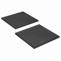
IC CYCLONE III FPGA 25K 256 UBGA
Manufacturer
Altera
Series
Cyclone® IIIr
Datasheets
1.EP3C5F256C8N.pdf
(5 pages)
2.EP3C5F256C8N.pdf
(34 pages)
3.EP3C5F256C8N.pdf
(66 pages)
4.EP3C5F256C8N.pdf
(14 pages)
5.EP3C5F256C8N.pdf
(76 pages)
6.EP3C25U256I7.pdf
(274 pages)
Specifications of EP3C25U256I7
Number Of Logic Elements/cells
24624
Number Of Labs/clbs
1539
Total Ram Bits
608256
Number Of I /o
156
Voltage - Supply
1.15 V ~ 1.25 V
Mounting Type
Surface Mount
Operating Temperature
-40°C ~ 100°C
Package / Case
256-UBGA
Family Name
Cyclone III
Number Of Logic Blocks/elements
24624
# I/os (max)
156
Frequency (max)
437.5MHz
Process Technology
65nm
Operating Supply Voltage (typ)
1.2V
Logic Cells
24624
Ram Bits
608256
Operating Supply Voltage (min)
1.15V
Operating Supply Voltage (max)
1.25V
Operating Temp Range
-40C to 100C
Operating Temperature Classification
Industrial
Mounting
Surface Mount
Pin Count
256
Package Type
UFBGA
For Use With
544-2370 - KIT STARTER CYCLONE III EP3C25
Lead Free Status / RoHS Status
Contains lead / RoHS non-compliant
Number Of Gates
-
Lead Free Status / Rohs Status
Not Compliant
Available stocks
Company
Part Number
Manufacturer
Quantity
Price

Company:
Part Number:
EP3C25U256I7N
Manufacturer:
ALTERA
Quantity:
220


2–10
Table 2–12. Hysteresis Specifications for Schmitt Trigger Input in Cyclone III LS Devices
Table 2–13. Cyclone III LS Devices Single-Ended I/O Standard Specifications
Cyclone III Device Handbook, Volume 2
V
3.3-V LVTTL
3.3-V LVCMOS
3.0-V LVTTL
3.0-V LVCMOS
2.5-V LVTTL and
LVCMOS
1.8-V LVTTL and
LVCMOS
1.5-V LVCMOS
1.2-V LVCMOS
PCI
PCI-X
Notes to
(1) AC load CL = 10 pF.
(2) For more information about interfacing Cyclone III LS devices with 3.3-, 3.0-, and 2.5-V LVTTL/LVCMOS I/O standards,
S CHM ITT
I/O Standard
Symbol
refer to
Table
(2)
AN 447: Interfacing Cyclone III and Cyclone iV Devices with 3.3/3.0/2.5-V LVTTL and LVCMOS I/O
(2)
(2)
2–13:
(2)
(2)
Hysteresis for Schmitt trigger
input
3.135
3.135
2.375
1.425
2.85
2.85
1.71
1.14
2.85
2.85
Min
Schmitt Trigger Input
Cyclone III LS devices support Schmitt trigger input on TDI, TMS, TCK, nSTATUS,
nCONFIG, nCE, CONF_DONE, and DCLK pins. A Schmitt trigger feature introduces
hysteresis to the input signal for improved noise immunity, especially for signals with
a slow edge rate.
range for Schmitt trigger inputs in Cyclone III LS devices.
I/O Standard Specifications
The following tables list input voltage sensitivities (V
(V
supported by Cyclone III LS devices.
Table 2–13
specifications.
OH
Parameter
V
and V
CC IO
Typ
3.3
3.3
3.0
3.0
2.5
1.8
1.5
1.2
3.0
3.0
(V)
OL
through
3.465
3.465
2.625
1.575
Max
3.15
3.15
1.89
1.26
3.15
3.15
), and current drive characteristics (I
Table 2–12
–0.3
–0.3
–0.3
–0.3
–0.3
–0.3
Min
—
—
—
—
Table 2–18
V
IL
(V)
0.35 *
0.35 *
0.35 *
V
V
V
V
0.30*
0.35*
Conditions
Max
V
V
V
V
V
CC IO
CC IO
CC IO
CC IO
0.8
0.8
0.8
0.8
0.7
CCIO
CCIO
CCIO
CCIO
CCIO
lists the hysteresis specifications across supported V
= 3.3 V
= 2.5 V
= 1.8 V
= 1.5 V
provide Cyclone III LS devices I/O standard
0.65 *
0.65 *
0.65 *
0.50*
0.50*
Min
V
V
V
V
V
1.7
1.7
1.7
1.7
1.7
CC IO
CC IO
CC IO
CC IO
CC IO
V
IH
Minimum
V
V
V
V
V
V
V
(V)
C CIO
C CIO
C CIO
C CIO
C CIO
C CIO
C CIO
Max
2.25
200
200
140
110
3.6
3.6
+ 0.3
+ 0.3
+ 0.3
+ 0.3
+ 0.3
+ 0.3
+ 0.3
(Note 1)
OH
0.25 * V
0.25 * V
0.1 * V
0.1 * V
and I
V
Chapter 2: Cyclone III LS Device Data Sheet
Max
0.45
0.45
0.45
IH
0.2
0.2
0.4
OL
Typical
(V)
and V
—
—
—
—
OL
CC IO
CC IO
C CIO
C CIO
© December 2009 Altera Corporation
) for various I/O standards
Systems.
IL
V
0.75 * V
0.75 * V
V
V
0.9 * V
0.9 * V
), output voltage
CC IO
C CIO
C CIO
V
Min
O H
2.4
2.4
2.0
– 0.45
– 0.2
– 0.2
(V)
Maximum
C CIO
C CIO
Electrical Characteristics
CC IO
CC IO
—
—
—
—
(mA)
0.1
1.5
1.5
I
4
2
4
1
2
2
2
O L
Unit
(mA)
–0.1
–0.5
–0.5
mV
mV
mV
mV
CCIO
–4
–2
–4
–1
–2
–2
–2
I
O H
Related parts for EP3C25U256I7
Image
Part Number
Description
Manufacturer
Datasheet
Request
R

Part Number:
Description:
CYCLONE II STARTER KIT EP2C20N
Manufacturer:
Altera
Datasheet:


Part Number:
Description:
CPLD, EP610 Family, ECMOS Process, 300 Gates, 16 Macro Cells, 16 Reg., 16 User I/Os, 5V Supply, 35 Speed Grade, 24DIP
Manufacturer:
Altera Corporation
Datasheet:
Part Number:
Description:
CPLD, EP610 Family, ECMOS Process, 300 Gates, 16 Macro Cells, 16 Reg., 16 User I/Os, 5V Supply, 15 Speed Grade, 24DIP
Manufacturer:
Altera Corporation
Datasheet:
Part Number:
Description:
Manufacturer:
Altera Corporation
Datasheet:
Part Number:
Description:
CPLD, EP610 Family, ECMOS Process, 300 Gates, 16 Macro Cells, 16 Reg., 16 User I/Os, 5V Supply, 30 Speed Grade, 24DIP
Manufacturer:
Altera Corporation
Datasheet:
Part Number:
Description:
High-performance, low-power erasable programmable logic devices with 8 macrocells, 10ns
Manufacturer:
Altera Corporation
Datasheet:
Part Number:
Description:
High-performance, low-power erasable programmable logic devices with 8 macrocells, 7ns
Manufacturer:
Altera Corporation
Datasheet:
Part Number:
Description:
Classic EPLD
Manufacturer:
Altera Corporation
Datasheet:
Part Number:
Description:
High-performance, low-power erasable programmable logic devices with 8 macrocells, 10ns
Manufacturer:
Altera Corporation
Datasheet:
Part Number:
Description:
Manufacturer:
Altera Corporation
Datasheet:
Part Number:
Description:
Manufacturer:
Altera Corporation
Datasheet:
Part Number:
Description:
Manufacturer:
Altera Corporation
Datasheet:
Part Number:
Description:
CPLD, EP610 Family, ECMOS Process, 300 Gates, 16 Macro Cells, 16 Reg., 16 User I/Os, 5V Supply, 25 Speed Grade, 24DIP
Manufacturer:
Altera Corporation
Datasheet: