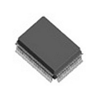
IDT82V2108PXG8 IDT, Integrated Device Technology Inc, IDT82V2108PXG8 Datasheet - Page 29

IDT82V2108PXG8
Manufacturer Part Number
IDT82V2108PXG8
Description
IC FRAMER T1/J1/E1 8CH 128-PQFP
Manufacturer
IDT, Integrated Device Technology Inc
Datasheet
1.IDT82V2108PX8.pdf
(292 pages)
Specifications of IDT82V2108PXG8
Controller Type
T1/E1/J1 Framer
Interface
Parallel
Voltage - Supply
2.97 V ~ 3.63 V
Current - Supply
160mA
Operating Temperature
-40°C ~ 85°C
Mounting Type
Surface Mount
Package / Case
128-MQFP, 128-PQFP
Screening Level
Industrial
Mounting
Surface Mount
Operating Temperature (min)
-40C
Operating Temperature (max)
85C
Lead Free Status / RoHS Status
Lead free / RoHS Compliant
Other names
82V2108PXG8
Available stocks
Company
Part Number
Manufacturer
Quantity
Price
Company:
Part Number:
IDT82V2108PXG8
Manufacturer:
IDT, Integrated Device Technology Inc
Quantity:
10 000
- Current page: 29 of 292
- Download datasheet (3Mb)
IDT82V2108
3.2.2.2
Processor is searching for SF/ESF synchronization. Once the SF/ESF is
synchronized, the buffer is relinquished by the Frame Processor and the
Frame Processor continues to monitor the errors. When the FAS error
ratio exceeds the criteria configured in the M2O[1:0] (b7~6, T1/J1-
020H), it is out of frame.
When there are conditions meeting the interrupt sources, the corre-
Table 5: Interrupt Sources in the T1/J1 Frame Processor
Functional Description
No.
1 The frame alignment mimic pattern is detected in the received data stream.
2 The SF / ESF synchronization is acquired.
3 The position of the new frame alignment pattern differs from the position of the
4 One bit error is detected in frame alignment pattern.
5 Two or more bit errors are detected in one frame alignment pattern.
6 In the SF format, one bit error is detected in frame alignment pattern.
A 4-frame capacity buffer is used to store the data when the Frame
The interrupt sources in this block are summarized in Table - 5.
previous one.
In the ESF format, the received CRC-6 is not equal to the local calculated CRC-6.
Out Of Synchronization Detection & Interrupt
Sources
19
sponding Status bit will be asserted high. When there is a transition (‘1’
to ‘0’ or ‘0’ to ‘1’) on the Status bit, the corresponding Status Interrupt
Indication bit will be set to logic 1 (If the Status bit does not exist, the
source will cause its Status Interrupt Indication bit to be logic 1 directly)
and the Status Interrupt Indication bit will be cleared when it is read. A
logic 1 in the Status Interrupt Indication bit indicates an interrupt
occurred. The interrupt is reported by the INT pin if its Status Interrupt
Enable bit was set to logic 1.
INFR (b0, T1/J1-022H) INFRI (b2, T1/J1-022H) INFRE (b0, T1/J1-021H)
MFP (b1, T1/J1-022H) MFPI (b3, T1/J1-022H)
Status Bit
-
-
-
-
COFAI (b7, T1/J1-022H) COFAE (b5, T1/J1-021H)
Interrupt Indication Bit
FERI (b6, T1/J1-022H)
SFEI (b4, T1/J1-022H)
BEEI (b5, T1/J1-022H)
T1 / E1 / J1 OCTAL FRAMER
MFPE (b1, T1/J1-021H)
FERE (b4, T1/J1-021H)
SFEE (b2, T1/J1-021H)
BEEE (b3, T1/J1-021H)
Interrupt Enable Bit
March 5, 2009
Related parts for IDT82V2108PXG8
Image
Part Number
Description
Manufacturer
Datasheet
Request
R

Part Number:
Description:
TRANSLATION DEVICE DPI 80-PQFP
Manufacturer:
IDT, Integrated Device Technology Inc
Datasheet:

Part Number:
Description:
IDT PART
Manufacturer:
IDT, Integrated Device Technology Inc
Datasheet:

Part Number:
Description:
IC LIU T1/E1/J1 OCTAL 256PBGA
Manufacturer:
IDT, Integrated Device Technology Inc
Datasheet:

Part Number:
Description:
IC FREQ TIMING GENERATOR 28TSSOP
Manufacturer:
IDT, Integrated Device Technology Inc
Datasheet:

Part Number:
Description:
IC CLK DVR PLL 1:10 40VFQFPN
Manufacturer:
IDT, Integrated Device Technology Inc
Datasheet:

Part Number:
Description:
IC CLK FANOUT BUFFER 1:18 32LQFP
Manufacturer:
IDT, Integrated Device Technology Inc
Datasheet:

Part Number:
Description:
IC CLK FANOUT BUFFER 1:18 32LQFP
Manufacturer:
IDT, Integrated Device Technology Inc
Datasheet:

Part Number:
Description:
IC CK505 VREG/RES 56TSSOP
Manufacturer:
IDT, Integrated Device Technology Inc
Datasheet:

Part Number:
Description:
IC SDRAM CLK DVR 1:10 48-TSSOP
Manufacturer:
IDT, Integrated Device Technology Inc
Datasheet:

Part Number:
Description:
IC CLK DVR PLL 1:10 48TSSOP
Manufacturer:
IDT, Integrated Device Technology Inc
Datasheet:

Part Number:
Description:
IC FLEXPC CLK PROGR P4 56-TSSOP
Manufacturer:
IDT, Integrated Device Technology Inc
Datasheet:

Part Number:
Description:
IC FLEXPC CLK PROGR P4 56-TSSOP
Manufacturer:
IDT, Integrated Device Technology Inc
Datasheet:

Part Number:
Description:
IC FLEXPC CLK PROGR P4 56-SSOP
Manufacturer:
IDT, Integrated Device Technology Inc
Datasheet:

Part Number:
Description:
IC PLL CLK DRIVER 2.5V 28-TSSOP
Manufacturer:
IDT, Integrated Device Technology Inc
Datasheet:

Part Number:
Description:
IC CLOCK DRIVER 2.5V 24-TSSOP
Manufacturer:
IDT, Integrated Device Technology Inc
Datasheet:


