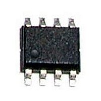
A25L040O-F AMIC, A25L040O-F Datasheet - Page 22

A25L040O-F
Manufacturer Part Number
A25L040O-F
Description
58T1309
Manufacturer
AMIC
Datasheet
1.A25L040-F.pdf
(39 pages)
Specifications of A25L040O-F
Memory Type
Flash
Memory Size
4Mbit
Memory Configuration
4M X 1
Interface Type
Serial, SPI
Clock Frequency
100MHz
Supply Voltage Range
2.7V To 3.6V
Memory Case Style
SOIC
No. Of Pins
8
Rohs Compliant
Yes
Available stocks
Company
Part Number
Manufacturer
Quantity
Price
Part Number:
A25L040O-F
Manufacturer:
AMIC
Quantity:
20 000
Deep Power-down (DP)
Executing the Deep Power-down (DP) instruction is the only
way to put the device in the lowest consumption mode (the
Deep Power-down mode). It can also be used as an extra
software protection mechanism, while the device is not in
active use, since in this mode, the device ignores all Write,
Program and Erase instructions.
Driving Chip Select (
the device in the Standby mode (if there is no internal cycle
currently in progress). But this mode is not the Deep
Power-down mode. The Deep Power-down mode can only be
entered by executing the Deep Power-down (DP) instruction,
to reduce the standby current (from I
DC Characteristics Table.).
Once the device has entered the Deep Power-down mode, all
instructions are ignored except the Release from Deep
Power-down and Read Electronic Signature (RES) instruction.
This releases the device from this mode. The Release from
Deep Power-down and Read Electronic Signature (RES)
instruction also allows the Electronic Signature of the device
to be output on Serial Data Output (DO).
Figure 16. Deep Power-down (DP) Instruction Sequence
(October, 2010, Version 1.2)
DIO
S
C
S
) High deselects the device, and puts
0
1 2 3 4 5 6 7
CC1
Instruction
to I
CC2
, as specified in
21
The Deep Power-down mode automatically stops at
Power-down, and the device always Powers-up in the
Standby mode.
The Deep Power-down (DP) instruction is entered by driving
Chip Select (
Serial Data Input (DIO). Chip Select (
for the entire duration of the sequence. The instruction
sequence is shown in Figure 16.
Chip Select (
instruction code has been latched in, otherwise the Deep
Power-down (DP) instruction is not executed. As soon as
Chip Select (
before the supply current is reduced to I
Power-down mode is entered.
Any Deep Power-down (DP) instruction, while an Erase,
Program or Write cycle is in progress, is rejected without
having any effects on the cycle that is in progress.
Stand-by Mode
t
DP
S
S
S
) must be driven High after the eighth bit of the
) Low, followed by the instruction code on
) is driven High, it requires a delay of t
Deep Power-down Mode
AMIC Technology Corp.
A25L040 Series
S
) must be driven Low
CC2
and the Deep
DP


