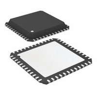
ATA6613P-PLQW Atmel, ATA6613P-PLQW Datasheet - Page 238

ATA6613P-PLQW
Manufacturer Part Number
ATA6613P-PLQW
Description
MCU W/LIN TXRX REG WTCHDG 48-QFN
Manufacturer
Atmel
Series
AVR® ATA66 LIN-SBCr
Datasheet
1.ATA6612-EK.pdf
(364 pages)
Specifications of ATA6613P-PLQW
Core Processor
AVR
Core Size
8-Bit
Speed
16MHz
Connectivity
I²C, LIN, SPI, UART/USART
Peripherals
Brown-out Detect/Reset, POR, PWM, WDT
Number Of I /o
23
Program Memory Size
16KB (16K x 8)
Program Memory Type
FLASH
Eeprom Size
512 x 8
Ram Size
1K x 8
Voltage - Supply (vcc/vdd)
2.7 V ~ 5.5 V
Data Converters
A/D 8x10b
Oscillator Type
Internal
Operating Temperature
-40°C ~ 125°C
Package / Case
48-QFN Exposed Pad
Processor Series
ATA6x
Core
AVR8
Data Bus Width
8 bit
Data Ram Size
1 KB
Interface Type
I2C, SPI, USART
Maximum Clock Frequency
16 MHz
Number Of Programmable I/os
23
Number Of Timers
3
Maximum Operating Temperature
+ 125 C
Mounting Style
SMD/SMT
Minimum Operating Temperature
- 40 C
On-chip Adc
10 bit, 8 Channel
Lead Free Status / RoHS Status
Lead free / RoHS Compliant
Available stocks
Company
Part Number
Manufacturer
Quantity
Price
Company:
Part Number:
ATA6613P-PLQW
Manufacturer:
ATMEL
Quantity:
5 000
Part Number:
ATA6613P-PLQW
Manufacturer:
ATMEL/爱特梅尔
Quantity:
20 000
- Current page: 238 of 364
- Download datasheet (7Mb)
6.19.5.5
6.19.6
6.19.6.1
6.19.6.2
238
Atmel ATA6612/ATA6613
TWI Register Description
Control Unit
TWI Bit Rate Register – TWBR
TWI Control Register – TWCR
The Control unit monitors the TWI bus and generates responses corresponding to settings in
the TWI Control Register (TWCR). When an event requiring the attention of the application
occurs on the TWI bus, the TWI Interrupt Flag (TWINT) is asserted. In the next clock cycle, the
TWI Status Register (TWSR) is updated with a status code identifying the event. The TWSR
only contains relevant status information when the TWI Interrupt Flag is asserted. At all other
times, the TWSR contains a special status code indicating that no relevant status information
is available. As long as the TWINT Flag is set, the SCL line is held low. This allows the appli-
cation software to complete its tasks before allowing the TWI transmission to continue.
The TWINT Flag is set in the following situations:
The TWCR is used to control the operation of the TWI. It is used to enable the TWI, to initiate
a Master access by applying a START condition to the bus, to generate a Receiver acknowl-
edge, to generate a stop condition, and to control halting of the bus while the data to be written
to the bus are written to the TWDR. It also indicates a write collision if data is attempted written
to TWDR while the register is inaccessible.
• After the TWI has transmitted a START/REPEATED START condition.
• After the TWI has transmitted SLA+R/W.
• After the TWI has transmitted an address byte.
• After the TWI has lost arbitration.
• After the TWI has been addressed by own slave address or general call.
• After the TWI has received a data byte.
• After a STOP or REPEATED START has been received while still addressed as a Slave.
• When a bus error has occurred due to an illegal START or STOP condition.
• Bits 7..0 – TWI Bit Rate Register
• Bit 7 – TWINT: TWI Interrupt Flag
Initial Value
Initial Value
Read/Write
Read/Write
TWBR selects the division factor for the bit rate generator. The bit rate generator is a fre-
quency divider which generates the SCL clock frequency in the Master modes. See
Rate Generator Unit” on page 237
This bit is set by hardware when the TWI has finished its current job and expects applica-
tion software response. If the I-bit in SREG and TWIE in TWCR are set, the MCU will jump
to the TWI Interrupt Vector.
Bit
Bit
TWBR7
TWINT
R/W
R/W
7
0
7
0
TWBR6
TWEA
R/W
R/W
6
0
6
0
TWBR5
TWSTA
R/W
R/W
5
0
5
0
for calculating bit rates.
TWBR4
TWSTO
R/W
R/W
4
0
4
0
TWBR3
TWWC
R/W
3
0
R
3
0
TWBR2
TWEN
R/W
R/W
2
0
2
0
TWBR1
R/W
1
0
R
1
–
0
TWBR0
TWIE
R/W
R/W
0
0
0
0
9111H–AUTO–01/11
TWBR
TWCR
“Bit
Related parts for ATA6613P-PLQW
Image
Part Number
Description
Manufacturer
Datasheet
Request
R

Part Number:
Description:
MCU W/LIN TXRX REG WTCHDG 48-QFN
Manufacturer:
Atmel
Datasheet:

Part Number:
Description:
Ata6613
Manufacturer:
ATMEL Corporation
Datasheet:

Part Number:
Description:
BOARD DEMO LIN-MCM FOR ATA6613
Manufacturer:
Atmel
Datasheet:

Part Number:
Description:
DEV KIT FOR AVR/AVR32
Manufacturer:
Atmel
Datasheet:

Part Number:
Description:
INTERVAL AND WIPE/WASH WIPER CONTROL IC WITH DELAY
Manufacturer:
ATMEL Corporation
Datasheet:

Part Number:
Description:
Low-Voltage Voice-Switched IC for Hands-Free Operation
Manufacturer:
ATMEL Corporation
Datasheet:

Part Number:
Description:
MONOLITHIC INTEGRATED FEATUREPHONE CIRCUIT
Manufacturer:
ATMEL Corporation
Datasheet:

Part Number:
Description:
AM-FM Receiver IC U4255BM-M
Manufacturer:
ATMEL Corporation
Datasheet:

Part Number:
Description:
Monolithic Integrated Feature Phone Circuit
Manufacturer:
ATMEL Corporation
Datasheet:

Part Number:
Description:
Multistandard Video-IF and Quasi Parallel Sound Processing
Manufacturer:
ATMEL Corporation
Datasheet:

Part Number:
Description:
High-performance EE PLD
Manufacturer:
ATMEL Corporation
Datasheet:

Part Number:
Description:
8-bit Flash Microcontroller
Manufacturer:
ATMEL Corporation
Datasheet:


