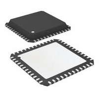
ATA6613P-PLQW Atmel, ATA6613P-PLQW Datasheet - Page 24

ATA6613P-PLQW
Manufacturer Part Number
ATA6613P-PLQW
Description
MCU W/LIN TXRX REG WTCHDG 48-QFN
Manufacturer
Atmel
Series
AVR® ATA66 LIN-SBCr
Datasheet
1.ATA6612-EK.pdf
(364 pages)
Specifications of ATA6613P-PLQW
Core Processor
AVR
Core Size
8-Bit
Speed
16MHz
Connectivity
I²C, LIN, SPI, UART/USART
Peripherals
Brown-out Detect/Reset, POR, PWM, WDT
Number Of I /o
23
Program Memory Size
16KB (16K x 8)
Program Memory Type
FLASH
Eeprom Size
512 x 8
Ram Size
1K x 8
Voltage - Supply (vcc/vdd)
2.7 V ~ 5.5 V
Data Converters
A/D 8x10b
Oscillator Type
Internal
Operating Temperature
-40°C ~ 125°C
Package / Case
48-QFN Exposed Pad
Processor Series
ATA6x
Core
AVR8
Data Bus Width
8 bit
Data Ram Size
1 KB
Interface Type
I2C, SPI, USART
Maximum Clock Frequency
16 MHz
Number Of Programmable I/os
23
Number Of Timers
3
Maximum Operating Temperature
+ 125 C
Mounting Style
SMD/SMT
Minimum Operating Temperature
- 40 C
On-chip Adc
10 bit, 8 Channel
Lead Free Status / RoHS Status
Lead free / RoHS Compliant
Available stocks
Company
Part Number
Manufacturer
Quantity
Price
Company:
Part Number:
ATA6613P-PLQW
Manufacturer:
ATMEL
Quantity:
5 000
Part Number:
ATA6613P-PLQW
Manufacturer:
ATMEL/爱特梅尔
Quantity:
20 000
- Current page: 24 of 364
- Download datasheet (7Mb)
5. Electrical Characteristics (Continued)
5V < V
24
*) Type means: A = 100% tested, B = 100% correlation tested, C = Characterized on samples, D = Design parameter
10.10
10.1
10.2
10.3
10.4
10.5
10.6
10.7
10.8
10.9
11.1
11.2
No.
10
11
S
< 27V, –40°C < T
Parameters
Internal Timers
Dominant time for
wake-up via LIN bus
Time delay for mode
change from Fail-safe
into Normal Mode via
EN pin
Time delay for mode
change from Normal
Mode to Sleep Mode via
EN pin
TXD dominant time-out
time
Time delay for mode
change from Silent
Mode into Normal Mode
via EN
Duty cycle 1
Duty cycle 2
Duty cycle 3
Duty cycle 4
Slope time falling and
rising edge at LIN
Receiver Electrical AC Parameters of the LIN Physical Layer
LIN Receiver, RXD Load Conditions (C
Propagation delay of
receiver
page
Symmetry of receiver
propagation delay rising
edge minus falling edge
Atmel ATA6612/ATA6613
27)
(Figure 5-1 on
case
< 125°C, –40°C < T
Test Conditions
V
V
V
V
V
TH
TH
V
t
D1 = t
TH
TH
V
t
D2 = t
TH
TH
V
t
D3 = t
TH
TH
V
t
D4 = t
V
V
t
V
t
Bit
Bit
Bit
Bit
rx_pd
rx_sym
LIN
EN
EN
TXD
EN
S
S
S
S
S
S
S
Rec(max)
Dom(max)
= 7.0V to 18V
Rec(min)
Dom(min)
= 7.6V to 18V
Rec(max)
Dom(max)
= 7.0V to 18V
Rec(min)
Dom(min)
= 7.6V to 18V
= 50µs
= 50µs
= 96µs
= 96µs
= 7.0V to 18V
= 7.0V to 18V
= 7.0V to 18V
= 5V
= 0V
= 5V
= 0V
= max(t
= 0V
bus_rec(min)
bus_rec(max)
bus_rec(min)
bus_rec(max)
= t
rx_pdr
= 0.422
= 0.389
= 0.744
= 0.284
= 0.778
= 0.251
= 0.581
= 0.616
rx_pdr
j
– t
< 150°C, unless otherwise specified. All values refer to GND pins
RXD
/(2
/(2
/(2
/(2
rx_pdf
, t
): 20pF
rx_pdf
V
V
t
t
V
V
V
V
t
t
V
Bit
V
Bit
Bit
Bit
S
S
S
S
S
S
S
S
)
)
)
)
)
RXD
RXD
TXD
Pin
LIN
LIN
LIN
LIN
LIN
LIN
EN
EN
EN
t
t
Symbol
SLOPE_rise
SLOPE_fall
t
t
t
t
rx_sym
t
rx_pd
t
norm
sleep
t
D1
D2
D3
D4
dom
bus
s_n
0.396
0.417
Min.
3.5
30
–2
5
2
6
5
Typ.
90
15
13
15
7
0.581
0.590
Max.
22.5
150
20
12
20
40
+2
6
9111H–AUTO–01/11
Unit
ms
µs
µs
µs
µs
µs
µs
µs
Type*
A
A
A
A
A
A
A
A
A
A
A
A
Related parts for ATA6613P-PLQW
Image
Part Number
Description
Manufacturer
Datasheet
Request
R

Part Number:
Description:
MCU W/LIN TXRX REG WTCHDG 48-QFN
Manufacturer:
Atmel
Datasheet:

Part Number:
Description:
Ata6613
Manufacturer:
ATMEL Corporation
Datasheet:

Part Number:
Description:
BOARD DEMO LIN-MCM FOR ATA6613
Manufacturer:
Atmel
Datasheet:

Part Number:
Description:
DEV KIT FOR AVR/AVR32
Manufacturer:
Atmel
Datasheet:

Part Number:
Description:
INTERVAL AND WIPE/WASH WIPER CONTROL IC WITH DELAY
Manufacturer:
ATMEL Corporation
Datasheet:

Part Number:
Description:
Low-Voltage Voice-Switched IC for Hands-Free Operation
Manufacturer:
ATMEL Corporation
Datasheet:

Part Number:
Description:
MONOLITHIC INTEGRATED FEATUREPHONE CIRCUIT
Manufacturer:
ATMEL Corporation
Datasheet:

Part Number:
Description:
AM-FM Receiver IC U4255BM-M
Manufacturer:
ATMEL Corporation
Datasheet:

Part Number:
Description:
Monolithic Integrated Feature Phone Circuit
Manufacturer:
ATMEL Corporation
Datasheet:

Part Number:
Description:
Multistandard Video-IF and Quasi Parallel Sound Processing
Manufacturer:
ATMEL Corporation
Datasheet:

Part Number:
Description:
High-performance EE PLD
Manufacturer:
ATMEL Corporation
Datasheet:

Part Number:
Description:
8-bit Flash Microcontroller
Manufacturer:
ATMEL Corporation
Datasheet:


