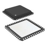
ATA6613P-PLQW Atmel, ATA6613P-PLQW Datasheet - Page 282

ATA6613P-PLQW
Manufacturer Part Number
ATA6613P-PLQW
Description
MCU W/LIN TXRX REG WTCHDG 48-QFN
Manufacturer
Atmel
Series
AVR® ATA66 LIN-SBCr
Datasheet
1.ATA6612-EK.pdf
(364 pages)
Specifications of ATA6613P-PLQW
Core Processor
AVR
Core Size
8-Bit
Speed
16MHz
Connectivity
I²C, LIN, SPI, UART/USART
Peripherals
Brown-out Detect/Reset, POR, PWM, WDT
Number Of I /o
23
Program Memory Size
16KB (16K x 8)
Program Memory Type
FLASH
Eeprom Size
512 x 8
Ram Size
1K x 8
Voltage - Supply (vcc/vdd)
2.7 V ~ 5.5 V
Data Converters
A/D 8x10b
Oscillator Type
Internal
Operating Temperature
-40°C ~ 125°C
Package / Case
48-QFN Exposed Pad
Processor Series
ATA6x
Core
AVR8
Data Bus Width
8 bit
Data Ram Size
1 KB
Interface Type
I2C, SPI, USART
Maximum Clock Frequency
16 MHz
Number Of Programmable I/os
23
Number Of Timers
3
Maximum Operating Temperature
+ 125 C
Mounting Style
SMD/SMT
Minimum Operating Temperature
- 40 C
On-chip Adc
10 bit, 8 Channel
Lead Free Status / RoHS Status
Lead free / RoHS Compliant
Available stocks
Company
Part Number
Manufacturer
Quantity
Price
Company:
Part Number:
ATA6613P-PLQW
Manufacturer:
ATMEL
Quantity:
5 000
Part Number:
ATA6613P-PLQW
Manufacturer:
ATMEL/爱特梅尔
Quantity:
20 000
- Current page: 282 of 364
- Download datasheet (7Mb)
6.22
6.22.1
6.22.2
6.22.3
282
debugWIRE On-chip Debug System
Atmel ATA6612/ATA6613
Features
Overview
Physical Interface
•
•
•
•
•
•
•
•
•
•
The debugWIRE On-chip debug system uses a One-wire, bi-directional interface to control the
program flow, execute AVR
memories.
When the debugWIRE Enable (DWEN) Fuse is programmed and Lock bits are unpro-
grammed, the debugWIRE system within the target device is activated. The RESET port pin is
configured as a wire-AND (open-drain) bi-directional I/O pin with pull-up enabled and becomes
the communication gateway between target and emulator.
Figure 6-113. The debugWIRE Setup
Figure 6-113
tor connector. The system clock is not affected by debugWIRE and will always be the clock
source selected by the CKSEL Fuses.
Complete Program Flow Control
Emulates All On-chip Functions, Both Digital and Analog, except RESET Pin
Real-time Operation
Symbolic Debugging Support (Both at C and Assembler Source Level, or for Other HLLs)
Unlimited Number of Program Break Points (Using Software Break Points)
Non-intrusive Operation
Electrical Characteristics Identical to Real Device
Automatic Configuration System
High-Speed Operation
Programming of Non-volatile Memories
shows the schematic of a target MCU, with debugWIRE enabled, and the emula-
dW
®
instructions in the CPU and to program the different non-volatile
GND
dW(RESE)
VCC
2.7 - 5.5
9111H–AUTO–01/11
Related parts for ATA6613P-PLQW
Image
Part Number
Description
Manufacturer
Datasheet
Request
R

Part Number:
Description:
MCU W/LIN TXRX REG WTCHDG 48-QFN
Manufacturer:
Atmel
Datasheet:

Part Number:
Description:
Ata6613
Manufacturer:
ATMEL Corporation
Datasheet:

Part Number:
Description:
BOARD DEMO LIN-MCM FOR ATA6613
Manufacturer:
Atmel
Datasheet:

Part Number:
Description:
DEV KIT FOR AVR/AVR32
Manufacturer:
Atmel
Datasheet:

Part Number:
Description:
INTERVAL AND WIPE/WASH WIPER CONTROL IC WITH DELAY
Manufacturer:
ATMEL Corporation
Datasheet:

Part Number:
Description:
Low-Voltage Voice-Switched IC for Hands-Free Operation
Manufacturer:
ATMEL Corporation
Datasheet:

Part Number:
Description:
MONOLITHIC INTEGRATED FEATUREPHONE CIRCUIT
Manufacturer:
ATMEL Corporation
Datasheet:

Part Number:
Description:
AM-FM Receiver IC U4255BM-M
Manufacturer:
ATMEL Corporation
Datasheet:

Part Number:
Description:
Monolithic Integrated Feature Phone Circuit
Manufacturer:
ATMEL Corporation
Datasheet:

Part Number:
Description:
Multistandard Video-IF and Quasi Parallel Sound Processing
Manufacturer:
ATMEL Corporation
Datasheet:

Part Number:
Description:
High-performance EE PLD
Manufacturer:
ATMEL Corporation
Datasheet:

Part Number:
Description:
8-bit Flash Microcontroller
Manufacturer:
ATMEL Corporation
Datasheet:


