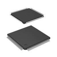
D12363VTE33 Renesas Electronics America, D12363VTE33 Datasheet - Page 28

D12363VTE33
Manufacturer Part Number
D12363VTE33
Description
MCU 3V 0K 120-TQFP
Manufacturer
Renesas Electronics America
Series
H8® H8S/2300r
Datasheet
1.DF2368VTE34V.pdf
(1044 pages)
Specifications of D12363VTE33
Core Processor
H8S/2000
Core Size
16-Bit
Speed
33MHz
Connectivity
I²C, IrDA, SCI, SmartCard
Peripherals
DMA, POR, PWM, WDT
Number Of I /o
84
Program Memory Type
ROMless
Ram Size
16K x 8
Voltage - Supply (vcc/vdd)
3 V ~ 3.6 V
Data Converters
A/D 10x10b, D/A 2x8b
Oscillator Type
Internal
Operating Temperature
-20°C ~ 75°C
Package / Case
120-TQFP, 120-VQFP
Lead Free Status / RoHS Status
Contains lead / RoHS non-compliant
Eeprom Size
-
Program Memory Size
-
Other names
HD6412363VTE33
HD6412363VTE33
HD6412363VTE33
Available stocks
Company
Part Number
Manufacturer
Quantity
Price
Company:
Part Number:
D12363VTE33V
Manufacturer:
Renesas Electronics America
Quantity:
10 000
- Current page: 28 of 1044
- Download datasheet (6Mb)
7.6
7.7
Section 8 Data Transfer Controller (DTC)
8.1
8.2
8.3
8.4
8.5
8.6
8.7
Rev.6.00 Mar. 18, 2009 Page xxvi of lviii
REJ09B0050-0600
7.5.16 Clearing Full Address Mode................................................................................ 286
Interrupt Sources............................................................................................................... 287
Usage Notes ...................................................................................................................... 288
7.7.1
7.7.2
7.7.3
7.7.4
7.7.5
7.7.6
7.7.7
7.7.8
Features............................................................................................................................. 293
Register Descriptions ........................................................................................................ 295
8.2.1
8.2.2
8.2.3
8.2.4
8.2.5
8.2.6
8.2.7
8.2.8
Activation Sources ............................................................................................................ 301
Location of Register Information and DTC Vector Table ................................................ 302
Operation .......................................................................................................................... 306
8.5.1
8.5.2
8.5.3
8.5.4
8.5.5
8.5.6
8.5.7
Procedures for Using DTC................................................................................................ 316
8.6.1
8.6.2
Examples of Use of the DTC ............................................................................................ 317
8.7.1
8.7.2
8.7.3
DMAC Register Access during Operation........................................................... 288
Module Stop......................................................................................................... 289
Write Data Buffer Function ................................................................................. 289
TEND Output....................................................................................................... 290
Activation by Falling Edge on DREQ Pin ........................................................... 291
Activation Source Acceptance ............................................................................. 291
Internal Interrupt after End of Transfer................................................................ 292
Channel Re-Setting .............................................................................................. 292
DTC Mode Register A (MRA) ............................................................................ 295
DTC Mode Register B (MRB)............................................................................. 297
DTC Source Address Register (SAR).................................................................. 297
DTC Destination Address Register (DAR).......................................................... 297
DTC Transfer Count Register A (CRA) .............................................................. 298
DTC Transfer Count Register B (CRB)............................................................... 298
DTC Enable Registers A to G (DTCERA to DTCERG) ..................................... 299
DTC Vector Register (DTVECR)........................................................................ 300
Normal Mode....................................................................................................... 308
Repeat Mode ........................................................................................................ 309
Block Transfer Mode ........................................................................................... 310
Chain Transfer ..................................................................................................... 311
Interrupts.............................................................................................................. 312
Operation Timing................................................................................................. 313
Number of DTC Execution States ....................................................................... 314
Activation by Interrupt......................................................................................... 316
Activation by Software ........................................................................................ 316
Normal Mode....................................................................................................... 317
Chain Transfer ..................................................................................................... 317
Chain Transfer when Counter = 0........................................................................ 318
................................................................... 293
Related parts for D12363VTE33
Image
Part Number
Description
Manufacturer
Datasheet
Request
R

Part Number:
Description:
KIT STARTER FOR M16C/29
Manufacturer:
Renesas Electronics America
Datasheet:

Part Number:
Description:
KIT STARTER FOR R8C/2D
Manufacturer:
Renesas Electronics America
Datasheet:

Part Number:
Description:
R0K33062P STARTER KIT
Manufacturer:
Renesas Electronics America
Datasheet:

Part Number:
Description:
KIT STARTER FOR R8C/23 E8A
Manufacturer:
Renesas Electronics America
Datasheet:

Part Number:
Description:
KIT STARTER FOR R8C/25
Manufacturer:
Renesas Electronics America
Datasheet:

Part Number:
Description:
KIT STARTER H8S2456 SHARPE DSPLY
Manufacturer:
Renesas Electronics America
Datasheet:

Part Number:
Description:
KIT STARTER FOR R8C38C
Manufacturer:
Renesas Electronics America
Datasheet:

Part Number:
Description:
KIT STARTER FOR R8C35C
Manufacturer:
Renesas Electronics America
Datasheet:

Part Number:
Description:
KIT STARTER FOR R8CL3AC+LCD APPS
Manufacturer:
Renesas Electronics America
Datasheet:

Part Number:
Description:
KIT STARTER FOR RX610
Manufacturer:
Renesas Electronics America
Datasheet:

Part Number:
Description:
KIT STARTER FOR R32C/118
Manufacturer:
Renesas Electronics America
Datasheet:

Part Number:
Description:
KIT DEV RSK-R8C/26-29
Manufacturer:
Renesas Electronics America
Datasheet:

Part Number:
Description:
KIT STARTER FOR SH7124
Manufacturer:
Renesas Electronics America
Datasheet:

Part Number:
Description:
KIT STARTER FOR H8SX/1622
Manufacturer:
Renesas Electronics America
Datasheet:

Part Number:
Description:
KIT DEV FOR SH7203
Manufacturer:
Renesas Electronics America
Datasheet:


