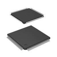
D12363VTE33 Renesas Electronics America, D12363VTE33 Datasheet - Page 57

D12363VTE33
Manufacturer Part Number
D12363VTE33
Description
MCU 3V 0K 120-TQFP
Manufacturer
Renesas Electronics America
Series
H8® H8S/2300r
Datasheet
1.DF2368VTE34V.pdf
(1044 pages)
Specifications of D12363VTE33
Core Processor
H8S/2000
Core Size
16-Bit
Speed
33MHz
Connectivity
I²C, IrDA, SCI, SmartCard
Peripherals
DMA, POR, PWM, WDT
Number Of I /o
84
Program Memory Type
ROMless
Ram Size
16K x 8
Voltage - Supply (vcc/vdd)
3 V ~ 3.6 V
Data Converters
A/D 10x10b, D/A 2x8b
Oscillator Type
Internal
Operating Temperature
-20°C ~ 75°C
Package / Case
120-TQFP, 120-VQFP
Lead Free Status / RoHS Status
Contains lead / RoHS non-compliant
Eeprom Size
-
Program Memory Size
-
Other names
HD6412363VTE33
HD6412363VTE33
HD6412363VTE33
Available stocks
Company
Part Number
Manufacturer
Quantity
Price
Company:
Part Number:
D12363VTE33V
Manufacturer:
Renesas Electronics America
Quantity:
10 000
- Current page: 57 of 1044
- Download datasheet (6Mb)
Table 16.2
Table 16.3
Table 16.4
Table 16.5
Table 16.6
Section 17 D/A Converter
Table 17.1
Table 17.2
Section 19 Flash Memory (0.35-μm F-ZTAT Version)
Table 19.1
Table 19.2
Table 19.3
Table 19.4
Table 19.5
Table 19.6
Table 19.7
Section 20 Flash Memory (0.18-μm F-ZTAT Version)
Table 20.1
Table 20.2
Table 20.3
Table 20.4
Table 20.5
Table 20.6
Table 20.7
Table 20.8 (1) Useable Area for Programming in User Program Mode ...................................... 770
Table 20.8 (2) Useable Area for Erasure in User Program Mode................................................ 772
Table 20.8 (3) Useable Area for Programming in User Boot Mode ............................................ 774
Table 20.8 (4) Useable Area for Erasure in User Boot Mode...................................................... 776
Table 20.9
Table 20.10 Software Protection ................................................................................................ 779
Table 20.11 Inquiry and Selection Commands .......................................................................... 786
Table 20.12 Programming/Erasing Command ........................................................................... 799
Table 20.13 Status Code............................................................................................................. 808
Table 20.14 Error Code .............................................................................................................. 809
Table 20.15 User Branch Processing Start Intervals .................................................................. 810
Analog Input Channels and Corresponding ADDR Registers................................ 665
A/D Conversion Time (Single Mode) .................................................................... 672
A/D Conversion Time (Scan Mode)....................................................................... 672
A/D Converter Interrupt Source ............................................................................. 673
Analog Pin Specifications ...................................................................................... 679
Pin Configuration ................................................................................................... 683
Control of D/A Conversion .................................................................................... 685
Differences between Boot Mode and User Program Mode.................................... 692
Pin Configuration ................................................................................................... 697
Erase Blocks........................................................................................................... 701
Setting On-Board Programming Mode................................................................... 702
Boot Mode Operation............................................................................................. 704
System Clock Frequencies for which Automatic Adjustment of LSI Bit Rate
is Possible............................................................................................................... 705
Flash Memory Operating States ............................................................................. 711
Comparison of Programming Modes ..................................................................... 721
Pin Configuration ................................................................................................... 726
Register/Parameter and Target Mode ..................................................................... 727
Parameters and Target Modes ................................................................................ 736
Setting On-Board Programming Mode................................................................... 748
System Clock Frequency for Automatic-Bit-Rate Adjustment by This LSI .......... 750
Executable MAT .................................................................................................... 769
Hardware Protection............................................................................................... 778
Rev.6.00 Mar. 18, 2009 Page lv of lviii
REJ09B0050-0600
Related parts for D12363VTE33
Image
Part Number
Description
Manufacturer
Datasheet
Request
R

Part Number:
Description:
KIT STARTER FOR M16C/29
Manufacturer:
Renesas Electronics America
Datasheet:

Part Number:
Description:
KIT STARTER FOR R8C/2D
Manufacturer:
Renesas Electronics America
Datasheet:

Part Number:
Description:
R0K33062P STARTER KIT
Manufacturer:
Renesas Electronics America
Datasheet:

Part Number:
Description:
KIT STARTER FOR R8C/23 E8A
Manufacturer:
Renesas Electronics America
Datasheet:

Part Number:
Description:
KIT STARTER FOR R8C/25
Manufacturer:
Renesas Electronics America
Datasheet:

Part Number:
Description:
KIT STARTER H8S2456 SHARPE DSPLY
Manufacturer:
Renesas Electronics America
Datasheet:

Part Number:
Description:
KIT STARTER FOR R8C38C
Manufacturer:
Renesas Electronics America
Datasheet:

Part Number:
Description:
KIT STARTER FOR R8C35C
Manufacturer:
Renesas Electronics America
Datasheet:

Part Number:
Description:
KIT STARTER FOR R8CL3AC+LCD APPS
Manufacturer:
Renesas Electronics America
Datasheet:

Part Number:
Description:
KIT STARTER FOR RX610
Manufacturer:
Renesas Electronics America
Datasheet:

Part Number:
Description:
KIT STARTER FOR R32C/118
Manufacturer:
Renesas Electronics America
Datasheet:

Part Number:
Description:
KIT DEV RSK-R8C/26-29
Manufacturer:
Renesas Electronics America
Datasheet:

Part Number:
Description:
KIT STARTER FOR SH7124
Manufacturer:
Renesas Electronics America
Datasheet:

Part Number:
Description:
KIT STARTER FOR H8SX/1622
Manufacturer:
Renesas Electronics America
Datasheet:

Part Number:
Description:
KIT DEV FOR SH7203
Manufacturer:
Renesas Electronics America
Datasheet:


