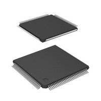
D12363VTE33 Renesas Electronics America, D12363VTE33 Datasheet - Page 54

D12363VTE33
Manufacturer Part Number
D12363VTE33
Description
MCU 3V 0K 120-TQFP
Manufacturer
Renesas Electronics America
Series
H8® H8S/2300r
Datasheet
1.DF2368VTE34V.pdf
(1044 pages)
Specifications of D12363VTE33
Core Processor
H8S/2000
Core Size
16-Bit
Speed
33MHz
Connectivity
I²C, IrDA, SCI, SmartCard
Peripherals
DMA, POR, PWM, WDT
Number Of I /o
84
Program Memory Type
ROMless
Ram Size
16K x 8
Voltage - Supply (vcc/vdd)
3 V ~ 3.6 V
Data Converters
A/D 10x10b, D/A 2x8b
Oscillator Type
Internal
Operating Temperature
-20°C ~ 75°C
Package / Case
120-TQFP, 120-VQFP
Lead Free Status / RoHS Status
Contains lead / RoHS non-compliant
Eeprom Size
-
Program Memory Size
-
Other names
HD6412363VTE33
HD6412363VTE33
HD6412363VTE33
Available stocks
Company
Part Number
Manufacturer
Quantity
Price
Company:
Part Number:
D12363VTE33V
Manufacturer:
Renesas Electronics America
Quantity:
10 000
- Current page: 54 of 1044
- Download datasheet (6Mb)
Section 6 Bus Controller (BSC)
Table 6.1
Table 6.2
Table 6.3
Table 6.4
Table 6.5
Table 6.6
Table 6.7
Table 6.8
Table 6.9
Section 7 DMA Controller (DMAC)
Table 7.1
Table 7.3
Table 7.4
Table 7.5
Table 7.6
Table 7.7
Table 7.8
Table 7.9
Table 7.10
Table 7.11
Table 7.12
Section 8 Data Transfer Controller (DTC)
Table 8.1
Table 8.2
Table 8.3
Table 8.4
Table 8.5
Table 8.6
Table 8.7
Table 8.8
Section 9 I/O Ports
Table 9.1
Table 9.2
Table 9.3
Table 9.4
Table 9.5
Rev.6.00 Mar. 18, 2009 Page lii of lviii
REJ09B0050-0600
Pin Configuration ................................................................................................... 121
Bus Specifications for Each Area (Basic Bus Interface) ........................................ 147
Data Buses Used and Valid Strobes ....................................................................... 152
Relation between Settings of Bits RMTS2 to RMTS0 and DRAM Space............. 165
Relation between Settings of Bits MXC2 to MXC0 and Address Multiplexing .... 166
DRAM Interface Pins............................................................................................. 167
Idle Cycles in Mixed Accesses to Normal Space and DRAM ............................... 201
Pin States in Idle Cycle .......................................................................................... 204
Pin States in Bus Released State ............................................................................ 207
Pin Configuration ................................................................................................... 215
DMAC Activation Sources .................................................................................... 241
DMAC Transfer Modes ......................................................................................... 244
Register Functions in Sequential Mode.................................................................. 246
Register Functions in Idle Mode ............................................................................ 249
Register Functions in Repeat Mode ....................................................................... 252
Register Functions in Single Address Mode .......................................................... 256
Register Functions in Normal Mode ...................................................................... 259
Register Functions in Block Transfer Mode........................................................... 262
DMAC Channel Priority Order .............................................................................. 282
Interrupt Sources and Priority Order ...................................................................... 287
Relationship between Activation Sources and DTCER Clearing........................... 301
Interrupt Sources, DTC Vector Addresses, and Corresponding DTCEs ................ 304
Chain Transfer Conditions ..................................................................................... 308
Register Function in Normal Mode........................................................................ 308
Register Function in Repeat Mode ......................................................................... 309
Register Function in Block Transfer Mode ............................................................ 310
DTC Execution Status............................................................................................ 314
Number of States Required for Each Execution Status .......................................... 315
Port Functions ........................................................................................................ 324
MOS Input Pull-Up States (Port A)........................................................................ 372
MOS Input Pull-Up States (Port B)........................................................................ 376
MOS Input Pull-Up States (Port C)........................................................................ 380
MOS Input Pull-Up States (Port D)........................................................................ 384
Related parts for D12363VTE33
Image
Part Number
Description
Manufacturer
Datasheet
Request
R

Part Number:
Description:
KIT STARTER FOR M16C/29
Manufacturer:
Renesas Electronics America
Datasheet:

Part Number:
Description:
KIT STARTER FOR R8C/2D
Manufacturer:
Renesas Electronics America
Datasheet:

Part Number:
Description:
R0K33062P STARTER KIT
Manufacturer:
Renesas Electronics America
Datasheet:

Part Number:
Description:
KIT STARTER FOR R8C/23 E8A
Manufacturer:
Renesas Electronics America
Datasheet:

Part Number:
Description:
KIT STARTER FOR R8C/25
Manufacturer:
Renesas Electronics America
Datasheet:

Part Number:
Description:
KIT STARTER H8S2456 SHARPE DSPLY
Manufacturer:
Renesas Electronics America
Datasheet:

Part Number:
Description:
KIT STARTER FOR R8C38C
Manufacturer:
Renesas Electronics America
Datasheet:

Part Number:
Description:
KIT STARTER FOR R8C35C
Manufacturer:
Renesas Electronics America
Datasheet:

Part Number:
Description:
KIT STARTER FOR R8CL3AC+LCD APPS
Manufacturer:
Renesas Electronics America
Datasheet:

Part Number:
Description:
KIT STARTER FOR RX610
Manufacturer:
Renesas Electronics America
Datasheet:

Part Number:
Description:
KIT STARTER FOR R32C/118
Manufacturer:
Renesas Electronics America
Datasheet:

Part Number:
Description:
KIT DEV RSK-R8C/26-29
Manufacturer:
Renesas Electronics America
Datasheet:

Part Number:
Description:
KIT STARTER FOR SH7124
Manufacturer:
Renesas Electronics America
Datasheet:

Part Number:
Description:
KIT STARTER FOR H8SX/1622
Manufacturer:
Renesas Electronics America
Datasheet:

Part Number:
Description:
KIT DEV FOR SH7203
Manufacturer:
Renesas Electronics America
Datasheet:


