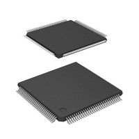
D12363VTE33 Renesas Electronics America, D12363VTE33 Datasheet - Page 50

D12363VTE33
Manufacturer Part Number
D12363VTE33
Description
MCU 3V 0K 120-TQFP
Manufacturer
Renesas Electronics America
Series
H8® H8S/2300r
Datasheet
1.DF2368VTE34V.pdf
(1044 pages)
Specifications of D12363VTE33
Core Processor
H8S/2000
Core Size
16-Bit
Speed
33MHz
Connectivity
I²C, IrDA, SCI, SmartCard
Peripherals
DMA, POR, PWM, WDT
Number Of I /o
84
Program Memory Type
ROMless
Ram Size
16K x 8
Voltage - Supply (vcc/vdd)
3 V ~ 3.6 V
Data Converters
A/D 10x10b, D/A 2x8b
Oscillator Type
Internal
Operating Temperature
-20°C ~ 75°C
Package / Case
120-TQFP, 120-VQFP
Lead Free Status / RoHS Status
Contains lead / RoHS non-compliant
Eeprom Size
-
Program Memory Size
-
Other names
HD6412363VTE33
HD6412363VTE33
HD6412363VTE33
Available stocks
Company
Part Number
Manufacturer
Quantity
Price
Company:
Part Number:
D12363VTE33V
Manufacturer:
Renesas Electronics America
Quantity:
10 000
- Current page: 50 of 1044
- Download datasheet (6Mb)
Section 17 D/A Converter
Figure 17.1 Block Diagram of D/A Converter .......................................................................... 682
Figure 17.2 Example of D/A Converter Operation.................................................................... 686
Section 19 Flash Memory (0.35-μm F-ZTAT Version)
Figure 19.1 Block Diagram of Flash Memory........................................................................... 690
Figure 19.2 Flash Memory State Transitions............................................................................. 691
Figure 19.3 Boot Mode.............................................................................................................. 693
Figure 19.4 User Program Mode ............................................................................................... 694
Figure 19.5 384-kbyte Flash Memory Block Configuration (Modes 3, 4, and 7)...................... 696
Figure 19.6 Programming/Erasing Flowchart Example in User Program Mode....................... 705
Figure 19.7 Program/Program-Verify Flowchart ...................................................................... 707
Figure 19.8 Erase/Erase-Verify Flowchart ................................................................................ 709
Figure 19.9 Power-On/Off Timing ............................................................................................ 714
Figure 19.10 Mode Transition Timing (Example: Boot Mode → User Mode ↔
User Program Mode).............................................................................................. 715
Section 20 Flash Memory (0.18-μm F-ZTAT Version)
Figure 20.1 Block Diagram of Flash Memory........................................................................... 719
Figure 20.2 Mode Transition of Flash Memory ........................................................................ 720
Figure 20.3 Flash Memory Configuration ................................................................................. 722
Figure 20.4 Block Division of User MAT................................................................................. 723
Figure 20.5 Overview of User Procedure Program ................................................................... 724
Figure 20.6 System Configuration in Boot Mode...................................................................... 749
Figure 20.7 Automatic-Bit-Rate Adjustment Operation of SCI ................................................ 749
Figure 20.8 Overview of Boot Mode State Transition Diagram................................................ 752
Figure 20.9 Programming/Erasing Overview Flow................................................................... 753
Figure 20.10 RAM Map when Programming/Erasing Is Executed ............................................. 754
Figure 20.11 Programming Procedure......................................................................................... 755
Figure 20.12 Erasing Procedure .................................................................................................. 762
Figure 20.13 Procedure for Programming User MAT in User Boot Mode ................................. 765
Figure 20.14 Procedure for Erasing User MAT in User Boot Mode ........................................... 767
Figure 20.15 Transitions to Error-Protection State...................................................................... 780
Figure 20.16 Switching between the User MAT and User Boot MAT ....................................... 781
Figure 20.17 Boot Program States............................................................................................... 783
Figure 20.18 Bit-Rate-Adjustment Sequence .............................................................................. 784
Figure 20.19 Communication Protocol Format ........................................................................... 785
Figure 20.20 New Bit-Rate Selection Sequence.......................................................................... 796
Figure 20.21 Programming Sequence.......................................................................................... 801
Figure 20.22 Erasure Sequence ................................................................................................... 804
Rev.6.00 Mar. 18, 2009 Page xlviii of lviii
REJ09B0050-0600
Related parts for D12363VTE33
Image
Part Number
Description
Manufacturer
Datasheet
Request
R

Part Number:
Description:
KIT STARTER FOR M16C/29
Manufacturer:
Renesas Electronics America
Datasheet:

Part Number:
Description:
KIT STARTER FOR R8C/2D
Manufacturer:
Renesas Electronics America
Datasheet:

Part Number:
Description:
R0K33062P STARTER KIT
Manufacturer:
Renesas Electronics America
Datasheet:

Part Number:
Description:
KIT STARTER FOR R8C/23 E8A
Manufacturer:
Renesas Electronics America
Datasheet:

Part Number:
Description:
KIT STARTER FOR R8C/25
Manufacturer:
Renesas Electronics America
Datasheet:

Part Number:
Description:
KIT STARTER H8S2456 SHARPE DSPLY
Manufacturer:
Renesas Electronics America
Datasheet:

Part Number:
Description:
KIT STARTER FOR R8C38C
Manufacturer:
Renesas Electronics America
Datasheet:

Part Number:
Description:
KIT STARTER FOR R8C35C
Manufacturer:
Renesas Electronics America
Datasheet:

Part Number:
Description:
KIT STARTER FOR R8CL3AC+LCD APPS
Manufacturer:
Renesas Electronics America
Datasheet:

Part Number:
Description:
KIT STARTER FOR RX610
Manufacturer:
Renesas Electronics America
Datasheet:

Part Number:
Description:
KIT STARTER FOR R32C/118
Manufacturer:
Renesas Electronics America
Datasheet:

Part Number:
Description:
KIT DEV RSK-R8C/26-29
Manufacturer:
Renesas Electronics America
Datasheet:

Part Number:
Description:
KIT STARTER FOR SH7124
Manufacturer:
Renesas Electronics America
Datasheet:

Part Number:
Description:
KIT STARTER FOR H8SX/1622
Manufacturer:
Renesas Electronics America
Datasheet:

Part Number:
Description:
KIT DEV FOR SH7203
Manufacturer:
Renesas Electronics America
Datasheet:


