YLCDRSK2378 Renesas Electronics America, YLCDRSK2378 Datasheet - Page 139
YLCDRSK2378
Manufacturer Part Number
YLCDRSK2378
Description
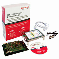
KIT DEV EVAL H8S/2378 LCD
Manufacturer
Renesas Electronics America
Series
H8®r
Datasheet
1.YR0K42378FC000BA.pdf
(1208 pages)
Specifications of YLCDRSK2378
Main Purpose
Displays, LCD Controller
Embedded
Yes, MCU, 16-Bit
Utilized Ic / Part
YLCDRSK2378
Primary Attributes
5.7" QVGA, Touch Screen
Secondary Attributes
Source Code on CD, Debugging Requires Emulator Cable E10A USB/JTAG
Lead Free Status / RoHS Status
Lead free / RoHS Compliant


3.1
The H8S/2378 0.18μm F-ZTAT Group and H8S/2378R 0.18μm F-ZTAT Group have six
operating modes (modes 1 to 5 and 7). The H8S/2377 and H8S/2377R have five operating modes
(modes 1 to 4 and 7). The H8S/2375 and H8S/2375R has four operating modes (modes 1, 2, 4, and
7). The H8S/2373 and H8S/2373R has two operating modes (modes 1 and 2). The operating mode
is selected by the setting of mode pins (MD2 to MD0).
Modes 1, 2, and 4 are externally expanded modes in which the CPU can access an external
memory and peripheral devices. In the externally expanded mode, each area can be switched to 8-
bit or 16-bit address space by the bus controller. If any one of the areas is set to 16-bit address
space, the bus mode is 16 bits. If all areas are set to 8-bit address space, the bus mode is 8 bits.
Mode 7 is a single-chip activation externally expanded mode in which the CPU can switch to
access an external memory and peripheral devices at the beginning of a program execution.
Mode 3 is a boot mode in which the flash memory can be programmed or erased. For details of the
boot mode, refer to section 21, Flash Memory (0.18-μm F-ZTAT Version), or section 20, Flash
Memory (0.35-μm F-ZTAT Version).
The settings for pins MD2 to MD0 should not be changed during operation.
Table 3.1
1 *
2 *
3
4
5 *
7
Notes: 1. Only modes 1 and 2 may be used on ROM-less versions.
MCU
Operating
Mode
1
1
2
2. Available only for the H8S/2378 0.18μm F-ZTAT Group and H8S/2378R 0.18μm
Operating Mode Selection
F-ZTAT Group.
0
0
0
1
1
1
MD2
MCU Operating Mode Selection
MD1
0
1
1
0
0
1
Section 3 MCU Operating Modes
1
0
1
0
1
1
MD0
Advanced
Advanced
Advanced
Advanced
Advanced
Advanced
CPU
Operating
Mode
Description
Expanded mode with
on-chip ROM disabled
Expanded mode with
on-chip ROM disabled
Boot mode
Expanded mode with
on-chip ROM enabled
User boot mode
Single-chip mode
Rev.7.00 Mar. 18, 2009 page 71 of 1136
Section 3 MCU Operating Modes
Disabled
Disabled
Enabled
Enabled
Enabled
Enabled
On-Chip
ROM
External Data Bus
Initial
Width
16 bits
8 bits
⎯
8 bits
⎯
⎯
REJ09B0109-0700
16 bits
16 bits
16 bits
16 bits
16 bits
16 bits
Max.
Value
Related parts for YLCDRSK2378
Image
Part Number
Description
Manufacturer
Datasheet
Request
R

Part Number:
Description:
KIT STARTER FOR M16C/29
Manufacturer:
Renesas Electronics America
Datasheet:

Part Number:
Description:
KIT STARTER FOR R8C/2D
Manufacturer:
Renesas Electronics America
Datasheet:

Part Number:
Description:
R0K33062P STARTER KIT
Manufacturer:
Renesas Electronics America
Datasheet:

Part Number:
Description:
KIT STARTER FOR R8C/23 E8A
Manufacturer:
Renesas Electronics America
Datasheet:

Part Number:
Description:
KIT STARTER FOR R8C/25
Manufacturer:
Renesas Electronics America
Datasheet:

Part Number:
Description:
KIT STARTER H8S2456 SHARPE DSPLY
Manufacturer:
Renesas Electronics America
Datasheet:

Part Number:
Description:
KIT STARTER FOR R8C38C
Manufacturer:
Renesas Electronics America
Datasheet:

Part Number:
Description:
KIT STARTER FOR R8C35C
Manufacturer:
Renesas Electronics America
Datasheet:

Part Number:
Description:
KIT STARTER FOR R8CL3AC+LCD APPS
Manufacturer:
Renesas Electronics America
Datasheet:
Part Number:
Description:
KIT STARTER FOR RX610
Manufacturer:
Renesas Electronics America
Datasheet:

Part Number:
Description:
KIT STARTER FOR R32C/118
Manufacturer:
Renesas Electronics America
Datasheet:

Part Number:
Description:
KIT DEV RSK-R8C/26-29
Manufacturer:
Renesas Electronics America
Datasheet:

Part Number:
Description:
KIT STARTER FOR SH7124
Manufacturer:
Renesas Electronics America
Datasheet:

Part Number:
Description:
KIT STARTER FOR H8SX/1622
Manufacturer:
Renesas Electronics America
Datasheet:

Part Number:
Description:
KIT DEV FOR SH7203
Manufacturer:
Renesas Electronics America
Datasheet: