YLCDRSK2378 Renesas Electronics America, YLCDRSK2378 Datasheet - Page 915
YLCDRSK2378
Manufacturer Part Number
YLCDRSK2378
Description
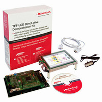
KIT DEV EVAL H8S/2378 LCD
Manufacturer
Renesas Electronics America
Series
H8®r
Datasheet
1.YR0K42378FC000BA.pdf
(1208 pages)
Specifications of YLCDRSK2378
Main Purpose
Displays, LCD Controller
Embedded
Yes, MCU, 16-Bit
Utilized Ic / Part
YLCDRSK2378
Primary Attributes
5.7" QVGA, Touch Screen
Secondary Attributes
Source Code on CD, Debugging Requires Emulator Cable E10A USB/JTAG
Lead Free Status / RoHS Status
Lead free / RoHS Compliant


3. When boot mode is used, the flash memory programming control program must be prepared in
4. Before branching to the programming control program, the chip terminates transfer operations
5. In boot mode, if flash memory contains data (all data is not 1), all blocks of flash memory are
Notes: 1. In boot mode, a part of the on-chip RAM area (H'FF8000 to H'FF87FF) is used by the
the host beforehand. Prepare a programming control program in accordance with the
description in section 20.7, Flash Memory Programming/Erasing.
by the SCI_1 (by clearing the RE and TE bits in SCR to 0), but the adjusted bit rate value
remains set in BRR. Therefore, the programming control program can still use it for transfer
of program data or verify data with the host. The TxD pin is high. The contents of the CPU
general registers are undefined immediately after branching to the programming control
program. These registers must be initialized at the beginning of the programming control
program, since the stack pointer (SP), in particular, is used implicitly in subroutine calls, etc.
erased. Boot mode is used for the initial programming in the on-board state or for a forcible
return when a program that is to be initiated in user program mode was accidentally erased and
could not be executed in user program mode.
2. Boot mode can be cleared by a reset. Release the reset by setting the MD pins, after
3. Do not change the MD pin input levels in boot mode.
4. All interrupts are disabled during programming or erasing of the flash memory.
boot program. Addresses H'FF8800 to H'FFBFFF is the area to which the
programming control program is transferred from the host. The boot program area
cannot be used until the execution state in boot mode switches to the programming
control program.
waiting at least 20 states since driving the reset pin low. Boot mode is also cleared
when the WDT overflow reset occurs.
Section 20 Flash Memory (0.35-μm F-ZTAT Version)
Rev.7.00 Mar. 18, 2009 page 847 of 1136
REJ09B0109-0700
Related parts for YLCDRSK2378
Image
Part Number
Description
Manufacturer
Datasheet
Request
R

Part Number:
Description:
KIT STARTER FOR M16C/29
Manufacturer:
Renesas Electronics America
Datasheet:

Part Number:
Description:
KIT STARTER FOR R8C/2D
Manufacturer:
Renesas Electronics America
Datasheet:

Part Number:
Description:
R0K33062P STARTER KIT
Manufacturer:
Renesas Electronics America
Datasheet:

Part Number:
Description:
KIT STARTER FOR R8C/23 E8A
Manufacturer:
Renesas Electronics America
Datasheet:

Part Number:
Description:
KIT STARTER FOR R8C/25
Manufacturer:
Renesas Electronics America
Datasheet:

Part Number:
Description:
KIT STARTER H8S2456 SHARPE DSPLY
Manufacturer:
Renesas Electronics America
Datasheet:

Part Number:
Description:
KIT STARTER FOR R8C38C
Manufacturer:
Renesas Electronics America
Datasheet:

Part Number:
Description:
KIT STARTER FOR R8C35C
Manufacturer:
Renesas Electronics America
Datasheet:

Part Number:
Description:
KIT STARTER FOR R8CL3AC+LCD APPS
Manufacturer:
Renesas Electronics America
Datasheet:
Part Number:
Description:
KIT STARTER FOR RX610
Manufacturer:
Renesas Electronics America
Datasheet:

Part Number:
Description:
KIT STARTER FOR R32C/118
Manufacturer:
Renesas Electronics America
Datasheet:

Part Number:
Description:
KIT DEV RSK-R8C/26-29
Manufacturer:
Renesas Electronics America
Datasheet:

Part Number:
Description:
KIT STARTER FOR SH7124
Manufacturer:
Renesas Electronics America
Datasheet:

Part Number:
Description:
KIT STARTER FOR H8SX/1622
Manufacturer:
Renesas Electronics America
Datasheet:

Part Number:
Description:
KIT DEV FOR SH7203
Manufacturer:
Renesas Electronics America
Datasheet: