YLCDRSK2378 Renesas Electronics America, YLCDRSK2378 Datasheet - Page 886
YLCDRSK2378
Manufacturer Part Number
YLCDRSK2378
Description
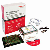
KIT DEV EVAL H8S/2378 LCD
Manufacturer
Renesas Electronics America
Series
H8®r
Datasheet
1.YR0K42378FC000BA.pdf
(1208 pages)
Specifications of YLCDRSK2378
Main Purpose
Displays, LCD Controller
Embedded
Yes, MCU, 16-Bit
Utilized Ic / Part
YLCDRSK2378
Primary Attributes
5.7" QVGA, Touch Screen
Secondary Attributes
Source Code on CD, Debugging Requires Emulator Cable E10A USB/JTAG
Lead Free Status / RoHS Status
Lead free / RoHS Compliant


Section 17 A/D Converter
17.7
17.7.1
Operation of the A/D converter can be disabled or enabled using the module stop control register.
The initial setting is for operation of the A/D converter to be halted. Register access is enabled by
clearing module stop mode. For details, refer to section 24, Power-Down Modes.
17.7.2
This LSI’s analog input is designed so that conversion precision is guaranteed for an input signal
for which the signal source impedance is 5 kΩ or less. This specification is provided to enable the
A/D converter’s sample-and-hold circuit input capacitance to be charged within the sampling time;
if the sensor output impedance exceeds 5 kΩ, charging may be insufficient and it may not be
possible to guarantee the A/D conversion accuracy. However, if a large capacitance is provided
externally for conversion in single mode, the input load will essentially comprise only the internal
input resistance of 10 kΩ, and the signal source impedance is ignored. However, since a low-pass
filter effect is obtained in this case, it may not be possible to follow an analog signal with a large
differential coefficient (e.g., 5 mV/μs or greater) (see figure 17.6). When converting a high-speed
analog signal or conversion in scan mode, a low-impedance buffer should be inserted.
Rev.7.00 Mar. 18, 2009 page 818 of 1136
REJ09B0109-0700
Sensor input
Usage Notes
Module Stop Mode Setting
Permissible Signal Source Impedance
Sensor output
impedance
Up to 5 kΩ
Low-pass
filter
C to 0.1 μF
Figure 17.6 Example of Analog Input Circuit
This LSI
Cin =
15 pF
Equivalent circuit of A/D converter
10 kΩ
20 pF
Related parts for YLCDRSK2378
Image
Part Number
Description
Manufacturer
Datasheet
Request
R

Part Number:
Description:
KIT STARTER FOR M16C/29
Manufacturer:
Renesas Electronics America
Datasheet:

Part Number:
Description:
KIT STARTER FOR R8C/2D
Manufacturer:
Renesas Electronics America
Datasheet:

Part Number:
Description:
R0K33062P STARTER KIT
Manufacturer:
Renesas Electronics America
Datasheet:

Part Number:
Description:
KIT STARTER FOR R8C/23 E8A
Manufacturer:
Renesas Electronics America
Datasheet:

Part Number:
Description:
KIT STARTER FOR R8C/25
Manufacturer:
Renesas Electronics America
Datasheet:

Part Number:
Description:
KIT STARTER H8S2456 SHARPE DSPLY
Manufacturer:
Renesas Electronics America
Datasheet:

Part Number:
Description:
KIT STARTER FOR R8C38C
Manufacturer:
Renesas Electronics America
Datasheet:

Part Number:
Description:
KIT STARTER FOR R8C35C
Manufacturer:
Renesas Electronics America
Datasheet:

Part Number:
Description:
KIT STARTER FOR R8CL3AC+LCD APPS
Manufacturer:
Renesas Electronics America
Datasheet:
Part Number:
Description:
KIT STARTER FOR RX610
Manufacturer:
Renesas Electronics America
Datasheet:

Part Number:
Description:
KIT STARTER FOR R32C/118
Manufacturer:
Renesas Electronics America
Datasheet:

Part Number:
Description:
KIT DEV RSK-R8C/26-29
Manufacturer:
Renesas Electronics America
Datasheet:

Part Number:
Description:
KIT STARTER FOR SH7124
Manufacturer:
Renesas Electronics America
Datasheet:

Part Number:
Description:
KIT STARTER FOR H8SX/1622
Manufacturer:
Renesas Electronics America
Datasheet:

Part Number:
Description:
KIT DEV FOR SH7203
Manufacturer:
Renesas Electronics America
Datasheet: