YLCDRSK2378 Renesas Electronics America, YLCDRSK2378 Datasheet - Page 914
YLCDRSK2378
Manufacturer Part Number
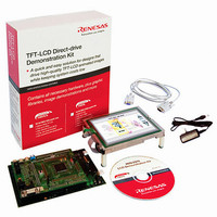
YLCDRSK2378
Description
KIT DEV EVAL H8S/2378 LCD
Manufacturer
Renesas Electronics America
Series
H8®r
Datasheet
1.YR0K42378FC000BA.pdf
(1208 pages)
Specifications of YLCDRSK2378
Main Purpose
Displays, LCD Controller
Embedded
Yes, MCU, 16-Bit
Utilized Ic / Part
YLCDRSK2378
Primary Attributes
5.7" QVGA, Touch Screen
Secondary Attributes
Source Code on CD, Debugging Requires Emulator Cable E10A USB/JTAG
Lead Free Status / RoHS Status
Lead free / RoHS Compliant


Section 20 Flash Memory (0.35-μm F-ZTAT Version)
20.6
In an on-board programming mode, programming, erasing, and verification for the on-chip flash
memory can be performed. There are two on-board programming modes: boot mode and user
program mode. Table 20.4 shows how to select boot mode. User program mode can be selected by
setting the control bits by software. For a diagram that shows mode transitions of flash memory,
see figure 20.2.
Table 20.4 Setting On-Board Programming Mode
Boot mode
20.6.1
When this LSI enters boot mode, the embedded boot program is started. The boot program
transfers the programming control program from the externally connected host to the on-chip
RAM via the SCI_1. When the flash memory is all erased, the programming control program is
executed.
Table 20.5 shows the boot mode operations between reset end and branching to the programming
control program.
1. When the boot program is initiated, the SCI_1 should be set to asynchronous mode, the chip
2. After matching the bit rates, the chip transmits one H'00 byte to the host to indicate the end of
Rev.7.00 Mar. 18, 2009 page 846 of 1136
REJ09B0109-0700
measures the low-level period of asynchronous SCI communication data (H'00) transmitted
continuously from the host. The chip then calculates the bit rate of transmission from the host,
and adjusts the SCI_1 bit rate to match that of the host. The transfer format is 8-bit data, 1 stop
bit, and no parity. The reset should end with the RxD pin high. The RxD and TxD pins should
be pulled up on the board if necessary. After the reset ends, it takes approximately 100 states
before the chip is ready to measure the low-level period.
bit rate adjustment. The host should confirm that this adjustment end indication (H'00) has
been received normally, and transmit one H'55 byte to the chip. If reception could not be
performed normally, initiate boot mode again by a reset. Depending on the host’s transfer bit
rate and system clock frequency of this LSI, there will be a discrepancy between the bit rates
of the host and the chip. To operate the SCI properly, set the host’s transfer bit rate and system
clock frequency of this LSI within the ranges listed in table 20.6.
On-Board Programming Modes
Boot Mode
Mode Setting
Single-chip activation expanded
mode with on-chip ROM enabled
MD2
0
MD1
1
MD0
1
Related parts for YLCDRSK2378
Image
Part Number
Description
Manufacturer
Datasheet
Request
R

Part Number:
Description:
KIT STARTER FOR M16C/29
Manufacturer:
Renesas Electronics America
Datasheet:

Part Number:
Description:
KIT STARTER FOR R8C/2D
Manufacturer:
Renesas Electronics America
Datasheet:

Part Number:
Description:
R0K33062P STARTER KIT
Manufacturer:
Renesas Electronics America
Datasheet:

Part Number:
Description:
KIT STARTER FOR R8C/23 E8A
Manufacturer:
Renesas Electronics America
Datasheet:

Part Number:
Description:
KIT STARTER FOR R8C/25
Manufacturer:
Renesas Electronics America
Datasheet:

Part Number:
Description:
KIT STARTER H8S2456 SHARPE DSPLY
Manufacturer:
Renesas Electronics America
Datasheet:

Part Number:
Description:
KIT STARTER FOR R8C38C
Manufacturer:
Renesas Electronics America
Datasheet:

Part Number:
Description:
KIT STARTER FOR R8C35C
Manufacturer:
Renesas Electronics America
Datasheet:

Part Number:
Description:
KIT STARTER FOR R8CL3AC+LCD APPS
Manufacturer:
Renesas Electronics America
Datasheet:
Part Number:
Description:
KIT STARTER FOR RX610
Manufacturer:
Renesas Electronics America
Datasheet:

Part Number:
Description:
KIT STARTER FOR R32C/118
Manufacturer:
Renesas Electronics America
Datasheet:

Part Number:
Description:
KIT DEV RSK-R8C/26-29
Manufacturer:
Renesas Electronics America
Datasheet:

Part Number:
Description:
KIT STARTER FOR SH7124
Manufacturer:
Renesas Electronics America
Datasheet:

Part Number:
Description:
KIT STARTER FOR H8SX/1622
Manufacturer:
Renesas Electronics America
Datasheet:

Part Number:
Description:
KIT DEV FOR SH7203
Manufacturer:
Renesas Electronics America
Datasheet: