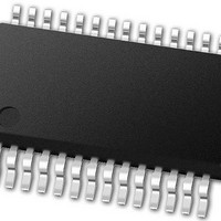
PIC24FJ64GB002-I/SS Microchip Technology, PIC24FJ64GB002-I/SS Datasheet - Page 118

PIC24FJ64GB002-I/SS
Manufacturer Part Number
PIC24FJ64GB002-I/SS
Description
16-bit, 16 MIPS, 64KB Flash, 8KB RAM, Nanowatt XLP, USB OTG 28 SSOP .209in TUBE
Manufacturer
Microchip Technology
Specifications of PIC24FJ64GB002-I/SS
Processor Series
PIC24
Core
PIC24F
Data Bus Width
16 bit
Program Memory Type
Flash
Program Memory Size
64 KB
Data Ram Size
8192 B
Interface Type
I2C, SPI, UART
Maximum Clock Frequency
32 MHz
Number Of Programmable I/os
21
Number Of Timers
5
Operating Supply Voltage
2 V to 3.6 V
Maximum Operating Temperature
+ 85 C
Mounting Style
SMD/SMT
Package / Case
SSOP-28
Development Tools By Supplier
MPLAB Integrated Development Environment
Minimum Operating Temperature
- 40 C
Operating Temperature Range
- 40 C to + 85 C
Supply Current (max)
300 mA
Lead Free Status / Rohs Status
Lead free / RoHS Compliant
Available stocks
Company
Part Number
Manufacturer
Quantity
Price
Part Number:
PIC24FJ64GB002-I/SS
Manufacturer:
MICROCHIP/微芯
Quantity:
20 000
- Current page: 118 of 352
- Download datasheet (3Mb)
PIC24FJ64GB004 FAMILY
9.2.2
Idle mode has these features:
• The CPU will stop executing instructions.
• The WDT is automatically cleared.
• The system clock source remains active. By
• If the WDT or FSCM is enabled, the LPRC will
The device will wake from Idle mode on any of these
events:
• Any interrupt that is individually enabled
• Any device Reset
• A WDT time-out
On wake-up from Idle mode, the clock is reapplied to
the CPU and instruction execution begins immediately,
starting with the instruction following the PWRSAV
instruction or the first instruction in the ISR.
9.2.3
Any interrupt that coincides with the execution of a
PWRSAV instruction (except for Deep Sleep mode) will
be held off until entry into Sleep or Idle mode has com-
pleted. The device will then wake-up from Sleep or Idle
mode.
9.2.4
In PIC24FJ64GB004 family devices, Deep Sleep mode
is intended to provide the lowest levels of power
consumption available, without requiring the use of
external switches to completely remove all power from
the device. Entry into Deep Sleep mode is completely
under software control. Exit from Deep Sleep mode can
be triggered from any of the following events:
• POR event
• MCLR event
• RTCC alarm (If the RTCC is present)
• External Interrupt 0
• Deep Sleep Watchdog Timer (DSWDT) time-out
In Deep Sleep mode, it is possible to keep the device
Real-Time Clock and Calendar (RTCC) running without
the loss of clock cycles.
The device has a dedicated Deep Sleep Brown-out
Reset (DSBOR) and a Deep Sleep Watchdog Timer
Reset (DSWDT) for monitoring voltage and time-out
events. The DSBOR and DSWDT are independent of
the standard BOR and WDT used with other
power-managed modes (Sleep, Idle and Doze).
DS39940D-page 118
default, all peripheral modules continue to operate
normally from the system clock source, but can
also be selectively disabled (see Section 9.4
“Selective Peripheral Module Control”).
also remain active.
IDLE MODE
INTERRUPTS COINCIDENT WITH
POWER SAVE INSTRUCTIONS
DEEP SLEEP MODE
9.2.4.1
Deep Sleep mode is entered by setting the DSEN bit in
the DSCON register, and then executing a SLEEP
instruction (PWRSAV #SLEEP_MODE) within one to three
instruction cycles to minimize the chance that Deep
Sleep will be spuriously entered.
If the PWRSAV command is not given within three
instruction cycles, the DSEN bit will be cleared by the
hardware and must be set again by the software before
entering Deep Sleep mode. The DSEN bit is also
automatically cleared when exiting the Deep Sleep
mode.
The sequence to enter Deep Sleep mode is:
1.
2.
3.
4.
5.
6.
Any time the DSEN bit is set, all bits in the DSWAKE
register will be automatically cleared.
Note:
Note:
If the application requires the Deep Sleep WDT,
enable it and configure its clock source (see
Section 9.2.4.7
details).
If the application requires Deep Sleep BOR,
enable it by programming the DSBOREN
Configuration bit (CW4<6>).
If the application requires wake-up from Deep
Sleep on RTCC alarm, enable and configure the
RTCC module (see Section 20.0 “Real-Time
Clock and Calendar (RTCC)” for more
information).
If needed, save any critical application context
data by writing it to the DSGPR0 and DSGPR1
registers (optional).
Enable Deep Sleep mode by setting the DSEN
bit (DSCON<15>).
Enter Deep Sleep mode by immediately issuing
a PWRSAV #0 instruction.
Since Deep Sleep mode powers down the
microcontroller by turning off the on-chip
V
capability is available only when operating
with the internal regulator enabled.
To re-enter Deep Sleep after a Deep Sleep
wake-up, allow a delay of at least 3 T
after clearing the RELEASE bit.
DDCORE
Entering Deep Sleep Mode
voltage regulator, Deep Sleep
“Deep
2010 Microchip Technology Inc.
Sleep
WDT”
for
CY
Related parts for PIC24FJ64GB002-I/SS
Image
Part Number
Description
Manufacturer
Datasheet
Request
R

Part Number:
Description:
Manufacturer:
Microchip Technology Inc.
Datasheet:

Part Number:
Description:
Manufacturer:
Microchip Technology Inc.
Datasheet:

Part Number:
Description:
Manufacturer:
Microchip Technology Inc.
Datasheet:

Part Number:
Description:
Manufacturer:
Microchip Technology Inc.
Datasheet:

Part Number:
Description:
Manufacturer:
Microchip Technology Inc.
Datasheet:

Part Number:
Description:
Manufacturer:
Microchip Technology Inc.
Datasheet:

Part Number:
Description:
Manufacturer:
Microchip Technology Inc.
Datasheet:

Part Number:
Description:
Manufacturer:
Microchip Technology Inc.
Datasheet:


