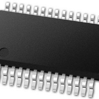
PIC24FJ64GB002-I/SS Microchip Technology, PIC24FJ64GB002-I/SS Datasheet - Page 197

PIC24FJ64GB002-I/SS
Manufacturer Part Number
PIC24FJ64GB002-I/SS
Description
16-bit, 16 MIPS, 64KB Flash, 8KB RAM, Nanowatt XLP, USB OTG 28 SSOP .209in TUBE
Manufacturer
Microchip Technology
Specifications of PIC24FJ64GB002-I/SS
Processor Series
PIC24
Core
PIC24F
Data Bus Width
16 bit
Program Memory Type
Flash
Program Memory Size
64 KB
Data Ram Size
8192 B
Interface Type
I2C, SPI, UART
Maximum Clock Frequency
32 MHz
Number Of Programmable I/os
21
Number Of Timers
5
Operating Supply Voltage
2 V to 3.6 V
Maximum Operating Temperature
+ 85 C
Mounting Style
SMD/SMT
Package / Case
SSOP-28
Development Tools By Supplier
MPLAB Integrated Development Environment
Minimum Operating Temperature
- 40 C
Operating Temperature Range
- 40 C to + 85 C
Supply Current (max)
300 mA
Lead Free Status / Rohs Status
Lead free / RoHS Compliant
Available stocks
Company
Part Number
Manufacturer
Quantity
Price
Part Number:
PIC24FJ64GB002-I/SS
Manufacturer:
MICROCHIP/微芯
Quantity:
20 000
- Current page: 197 of 352
- Download datasheet (3Mb)
18.0
PIC24FJ64GB004 family devices contain a full-speed
and low-speed compatible, On-The-Go (OTG) USB
Serial Interface Engine (SIE). The OTG capability
allows the device to act either as a USB peripheral
device or as a USB embedded host with limited host
capabilities. The OTG capability allows the device to
dynamically switch from device to host operation using
OTG’s Host Negotiation Protocol (HNP).
For more details on OTG operation, refer to the
“On-The-Go Supplement to the USB 2.0 Specification”,
published by the USB-IF. For more information on USB
operation,
Specification”, v2.0.
The USB OTG module offers these features:
• USB functionality in Device and Host modes, and
• 0.25% Accuracy using Internal Oscillator – No
• Software-selectable module speeds of full speed
• Support for all four USB transfer types: control,
• 16 bidirectional endpoints for a total of 32 unique
• DMA interface for data RAM access
• Queues up to sixteen unique endpoint transfers
• Integrated on-chip USB transceiver, with support
• Integrated V
• Configurations for on-chip bus pull-up and
A simplified block diagram of the USB OTG module is
shown in Figure 18-1.
2010 Microchip Technology Inc.
Note:
OTG capabilities for application-controlled mode
switching
External Crystal Required
(12 Mbps) or low speed (1.5 Mbps, available in
Host mode only)
interrupt, bulk and isochronous
endpoints
without servicing
for off-chip transceivers via a digital interface
comparators and boost generation, and support of
external V
through a digital interface
pull-down resistors
UNIVERSAL SERIAL BUS WITH
ON-THE-GO SUPPORT (USB
OTG)
This data sheet summarizes the features
of this group of PIC24F devices. It is not
intended to be a comprehensive reference
source. For more information, refer to the
“PIC24F
”Section 27. USB On-The-Go (OTG)”
(DS39721).
refer
BUS
BUS
comparators and regulators
generation with on-chip
to
Family
the
“Universal
Reference
Serial
Manual”,
PIC24FJ64GB004 FAMILY
Bus
The USB OTG module can function as a USB periph-
eral device or as a USB host, and may dynamically
switch between Device and Host modes under soft-
ware control. In either mode, the same data paths and
buffer descriptors are used for the transmission and
reception of data.
In discussing USB operation, this section will use a
controller-centric nomenclature for describing the direc-
tion of the data transfer between the microcontroller and
the USB. Rx (Receive) will be used to describe transfers
that move data from the USB to the microcontroller, and
Tx (Transmit) will be used to describe transfers that
move data from the microcontroller to the USB.
Table 18-1 shows the relationship between data
direction in this nomenclature and the USB tokens
exchanged.
TABLE 18-1:
This chapter presents the most basic operations
needed to implement USB OTG functionality in an
application. A complete and detailed discussion of the
USB protocol and its OTG supplement are beyond the
scope of this data sheet. It is assumed that the user
already has a basic understanding of USB architecture
and the latest version of the protocol.
Not all steps for proper USB operation (such as device
enumeration) are presented here. It is recommended
that application developers use an appropriate device
driver to implement all of the necessary features.
Microchip provides a number of application-specific
resources, such as USB firmware and driver support.
Refer to www.microchip.com/usb for the latest
firmware and driver support.
USB Mode
Device
Host
CONTROLLER-CENTRIC
DATA DIRECTION FOR USB
HOST OR TARGET
OUT or SETUP
Rx
IN
Direction
DS39940D-page 197
OUT or SETUP
Tx
IN
Related parts for PIC24FJ64GB002-I/SS
Image
Part Number
Description
Manufacturer
Datasheet
Request
R

Part Number:
Description:
Manufacturer:
Microchip Technology Inc.
Datasheet:

Part Number:
Description:
Manufacturer:
Microchip Technology Inc.
Datasheet:

Part Number:
Description:
Manufacturer:
Microchip Technology Inc.
Datasheet:

Part Number:
Description:
Manufacturer:
Microchip Technology Inc.
Datasheet:

Part Number:
Description:
Manufacturer:
Microchip Technology Inc.
Datasheet:

Part Number:
Description:
Manufacturer:
Microchip Technology Inc.
Datasheet:

Part Number:
Description:
Manufacturer:
Microchip Technology Inc.
Datasheet:

Part Number:
Description:
Manufacturer:
Microchip Technology Inc.
Datasheet:


