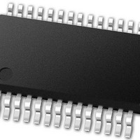
PIC24FJ64GB002-I/SS Microchip Technology, PIC24FJ64GB002-I/SS Datasheet - Page 133

PIC24FJ64GB002-I/SS
Manufacturer Part Number
PIC24FJ64GB002-I/SS
Description
16-bit, 16 MIPS, 64KB Flash, 8KB RAM, Nanowatt XLP, USB OTG 28 SSOP .209in TUBE
Manufacturer
Microchip Technology
Specifications of PIC24FJ64GB002-I/SS
Processor Series
PIC24
Core
PIC24F
Data Bus Width
16 bit
Program Memory Type
Flash
Program Memory Size
64 KB
Data Ram Size
8192 B
Interface Type
I2C, SPI, UART
Maximum Clock Frequency
32 MHz
Number Of Programmable I/os
21
Number Of Timers
5
Operating Supply Voltage
2 V to 3.6 V
Maximum Operating Temperature
+ 85 C
Mounting Style
SMD/SMT
Package / Case
SSOP-28
Development Tools By Supplier
MPLAB Integrated Development Environment
Minimum Operating Temperature
- 40 C
Operating Temperature Range
- 40 C to + 85 C
Supply Current (max)
300 mA
Lead Free Status / Rohs Status
Lead free / RoHS Compliant
Available stocks
Company
Part Number
Manufacturer
Quantity
Price
Part Number:
PIC24FJ64GB002-I/SS
Manufacturer:
MICROCHIP/微芯
Quantity:
20 000
- Current page: 133 of 352
- Download datasheet (3Mb)
10.4.5
The ability to control Peripheral Pin Selection intro-
duces several considerations into application design
that could be overlooked. This is particularly true for
several common peripherals that are available only as
remappable peripherals.
The main consideration is that the Peripheral Pin
Selects are not available on default pins in the device’s
default (Reset) state. Since all RPINRx registers reset
to ‘11111’ and all RPORx registers reset to ‘00000’, all
Peripheral Pin Select inputs are tied to V
Peripheral Pin Select outputs are disconnected.
This situation requires the user to initialize the device
with the proper peripheral configuration before any
other application code is executed. Since the IOLOCK
bit resets in the unlocked state, it is not necessary to
execute the unlock sequence after the device has
come out of Reset. For application safety, however, it is
best to set IOLOCK and lock the configuration after
writing to the control registers.
Because the unlock sequence is timing-critical, it must
be executed as an assembly language routine in the
same manner as changes to the oscillator configura-
tion. If the bulk of the application is written in C or
another high-level language, the unlock sequence
should be performed by writing in-line assembly.
Choosing the configuration requires the review of all
Peripheral Pin Selects and their pin assignments,
especially those that will not be used in the application.
In all cases, unused pin-selectable peripherals should
be disabled completely. Unused peripherals should
have their inputs assigned to an unused RPn pin
function. I/O pins with unused RPn functions should be
configured with the null peripheral output.
2010 Microchip Technology Inc.
Note:
CONSIDERATIONS FOR
PERIPHERAL PIN SELECTION
RP31 does not have to exist on a device
for the registers to be reset to it, or for
peripheral pin outputs to be tied to it.
SS
and all
PIC24FJ64GB004 FAMILY
The assignment of a peripheral to a particular pin does
not automatically perform any other configuration of the
pin’s I/O circuitry. In theory, this means adding a
pin-selectable output to a pin may mean inadvertently
driving an existing peripheral input when the output is
driven. Users must be familiar with the behavior of
other fixed peripherals that share a remappable pin and
know when to enable or disable them. To be safe, fixed
digital peripherals that share the same pin should be
disabled when not in use.
Along these lines, configuring a remappable pin for a
specific peripheral does not automatically turn that
feature on. The peripheral must be specifically
configured for operation and enabled, as if it were tied to
a fixed pin. Where this happens in the application code
(immediately following device Reset and peripheral
configuration or inside the main application routine)
depends on the peripheral and its use in the application.
A final consideration is that Peripheral Pin Select func-
tions neither override analog inputs, nor reconfigure
pins with analog functions for digital I/O. If a pin is
configured as an analog input on device Reset, it must
be explicitly reconfigured as digital I/O when used with
a Peripheral Pin Select.
Example 10-2 shows a configuration for bidirectional
communication with flow control using UART1. The
following input and output functions are used:
• Input Functions: U1RX, U1CTS
• Output Functions: U1TX, U1RTS
DS39940D-page 133
Related parts for PIC24FJ64GB002-I/SS
Image
Part Number
Description
Manufacturer
Datasheet
Request
R

Part Number:
Description:
Manufacturer:
Microchip Technology Inc.
Datasheet:

Part Number:
Description:
Manufacturer:
Microchip Technology Inc.
Datasheet:

Part Number:
Description:
Manufacturer:
Microchip Technology Inc.
Datasheet:

Part Number:
Description:
Manufacturer:
Microchip Technology Inc.
Datasheet:

Part Number:
Description:
Manufacturer:
Microchip Technology Inc.
Datasheet:

Part Number:
Description:
Manufacturer:
Microchip Technology Inc.
Datasheet:

Part Number:
Description:
Manufacturer:
Microchip Technology Inc.
Datasheet:

Part Number:
Description:
Manufacturer:
Microchip Technology Inc.
Datasheet:


