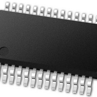
PIC24FJ64GB002-I/SS Microchip Technology, PIC24FJ64GB002-I/SS Datasheet - Page 211

PIC24FJ64GB002-I/SS
Manufacturer Part Number
PIC24FJ64GB002-I/SS
Description
16-bit, 16 MIPS, 64KB Flash, 8KB RAM, Nanowatt XLP, USB OTG 28 SSOP .209in TUBE
Manufacturer
Microchip Technology
Specifications of PIC24FJ64GB002-I/SS
Processor Series
PIC24
Core
PIC24F
Data Bus Width
16 bit
Program Memory Type
Flash
Program Memory Size
64 KB
Data Ram Size
8192 B
Interface Type
I2C, SPI, UART
Maximum Clock Frequency
32 MHz
Number Of Programmable I/os
21
Number Of Timers
5
Operating Supply Voltage
2 V to 3.6 V
Maximum Operating Temperature
+ 85 C
Mounting Style
SMD/SMT
Package / Case
SSOP-28
Development Tools By Supplier
MPLAB Integrated Development Environment
Minimum Operating Temperature
- 40 C
Operating Temperature Range
- 40 C to + 85 C
Supply Current (max)
300 mA
Lead Free Status / Rohs Status
Lead free / RoHS Compliant
Available stocks
Company
Part Number
Manufacturer
Quantity
Price
Part Number:
PIC24FJ64GB002-I/SS
Manufacturer:
MICROCHIP/微芯
Quantity:
20 000
- Current page: 211 of 352
- Download datasheet (3Mb)
The B-device then proceeds by pulsing the V
supply. Software should do this by setting PUVBUS
(U1CNFG2<4>). When an A-device detects SRP sig-
naling (either via the ATTACHIF (U1IR<6>) interrupt or
via the SESVDIF (U1OTGIR<3>) interrupt), the
A-device must restore the V
VBUSON (U1OTGCON<3>), or by setting the I/O port
controlling the external power source.
The B-device should not monitor the state of the V
supply while performing V
B-device does detect that the V
restored (via the SESVDIF (U1OTGIR<3>) interrupt),
the B-device must re-connect to the USB link by pulling
up D+ or D- (via the DPPULUP or DMPULUP).
The A-device must complete the SRP by driving USB
Reset signaling.
18.6.2
In USB OTG applications, a Dual Role Device (DRD) is
a device that is capable of being either a host or a
peripheral. Any OTG DRD must support Host
Negotiation Protocol (HNP).
HNP allows an OTG B-device to temporarily become
the USB host. The A-device must first enable the
B-device to follow HNP. Refer to the On-The-Go
Supplement to the USB 2.0 Specification for more
information regarding HNP. HNP may only be initiated
at full speed.
After being enabled for HNP by the A-device, the
B-device requests being the host any time that the USB
link is in Suspend state, by simply indicating a discon-
nect. This can be done in software by clearing
TABLE 18-3:
2010 Microchip Technology Inc.
If UVCMPSEL = 0
If UVCMPSEL = 1
VBUSVLD
VCMPST1
0
1
0
1
0
0
0
1
HOST NEGOTIATION PROTOCOL
(HNP)
EXTERNAL VBUS COMPARATOR STATES
VCMPST2
SESSVLD
BUS
BUS
0
0
1
1
0
0
1
1
supply pulsing. When the
supply by either setting
BUS
supply has been
V
V
V
V
A
BUS
B
BUS
_
_
SESSEND
SESS
SESS
< V
> V
1
0
0
0
_
_
B
VBUS
END
VLD
_
PIC24FJ64GB004 FAMILY
SESS
BUS
BUS
< V
_
< V
VLD
_
BUS
END
BUS
V
V
V
V
A
BUS
B
BUS
< V
_
_
< V
SESS
SESS
DPPULUP and DMPULUP. When the A-device detects
the disconnect condition (via the URSTIF (U1IR<0>)
interrupt), the A-device may allow the B-device to take
over as Host. The A-device does this by signaling con-
nect as a full-speed function. Software may accomplish
this by setting DPPULUP.
If the A-device responds instead with resume signaling,
the A-device remains as host. When the B-device
detects
(U1IR<6>), the B-device becomes host. The B-device
drives Reset signaling prior to using the bus.
When the B-device has finished in its role as Host, it
stops all bus activity and turns on its D+ pull-up resistor
by setting DPPULUP. When the A-device detects a
suspend condition (Idle for 3 ms), the A-device turns off
its D+ pull-up. The A-device may also power-down
V
detects the connect condition (via ATTACHIF), the
A-device resumes host operation, and drives Reset
signaling.
18.6.3
The external V
setting the UVCMPDIS bit (U1CNFG2<1>). This dis-
ables the internal V
need to attach V
The external comparator interface uses either the
VCMPST1 and VCMPST2 pins, or the VBUSVLD,
SESSVLD and SESSEND pins, based upon the setting
of the UVCMPSEL bit (U1CNFG2<5>). These pins are
digital inputs and should be set in the following patterns
(see Table 18-3), based on the current level of the
V
A
< V
> V
A
BUS
BUS
_
_
VBUS
_
SESS
_
B
VBUS
VLD
END
_
voltage.
supply to end the session. When the A-device
SESS
Bus Condition
_
_
< V
_
VLD
< V
VLD
the
VLD
_
EXTERNAL V
BUS
END
BUS
connect
BUS
BUS
Bus Condition
< V
< V
A
A
comparator option is enabled by
to the microcontroller’s V
_
BUS
_
VBUS
SESS
condition
comparators, removing the
_
BUS
_
VLD
VLD
COMPARATORS
DS39940D-page 211
(via
ATTACHIF
BUS
pin.
Related parts for PIC24FJ64GB002-I/SS
Image
Part Number
Description
Manufacturer
Datasheet
Request
R

Part Number:
Description:
Manufacturer:
Microchip Technology Inc.
Datasheet:

Part Number:
Description:
Manufacturer:
Microchip Technology Inc.
Datasheet:

Part Number:
Description:
Manufacturer:
Microchip Technology Inc.
Datasheet:

Part Number:
Description:
Manufacturer:
Microchip Technology Inc.
Datasheet:

Part Number:
Description:
Manufacturer:
Microchip Technology Inc.
Datasheet:

Part Number:
Description:
Manufacturer:
Microchip Technology Inc.
Datasheet:

Part Number:
Description:
Manufacturer:
Microchip Technology Inc.
Datasheet:

Part Number:
Description:
Manufacturer:
Microchip Technology Inc.
Datasheet:


