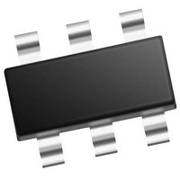
PIC10F322T-I/OT Microchip Technology, PIC10F322T-I/OT Datasheet - Page 147

PIC10F322T-I/OT
Manufacturer Part Number
PIC10F322T-I/OT
Description
896 B Flash, 64 B RAM, 4 I/O, 8bit ADC, PWM, CLC, DDS, CWG, TEMP Indicator, 2.3V
Manufacturer
Microchip Technology
Datasheet
1.PIC10F320-IOT.pdf
(210 pages)
Specifications of PIC10F322T-I/OT
Core
RISC
Processor Series
PIC10F
Data Bus Width
8 bit
Maximum Clock Frequency
31 KHz
Program Memory Size
512 B
Data Ram Size
64 B
Number Of Programmable I/os
4
Number Of Timers
2
Operating Temperature Range
- 40 C to + 85 C
Package / Case
SOT-23-6
Mounting Style
SMD/SMT
Maximum Operating Temperature
+ 85 C
Program Memory Type
Flash
Lead Free Status / Rohs Status
Details
Available stocks
Company
Part Number
Manufacturer
Quantity
Price
Company:
Part Number:
PIC10F322T-I/OT
Manufacturer:
VISHAY
Quantity:
11 490
Part Number:
PIC10F322T-I/OT
Manufacturer:
MICROCHIP/微芯
Quantity:
20 000
21.11 Configuring the CWG
The following steps illustrate how to properly configure
the CWG to ensure a synchronous start:
1.
2.
3.
4.
5.
6.
7.
8.
9.
21.11.1
The levels driven to the output pins, while the shutdown
input is true, are controlled by the GxASDLA and
GxASDLB
(Register
override level and GxASDLB controls the CWG1B
override level. The control bit logic level corresponds to
the output logic drive level while in the shutdown state.
The polarity control does not apply to the override level.
21.11.2
After an auto-shutdown event has occurred, there are
two ways to have resume operation:
• Software controlled
• Auto-restart
The restart method is selected with the GxARSEN bit
of the CWGxCON2 register. Waveforms of software
controlled and automatic restarts are shown in
Figure 21-5
2011 Microchip Technology Inc.
Ensure that the TRIS control bits corresponding
to CWGxA and CWGxB are set so that both are
configured as inputs.
Clear the GxEN bit, if not already cleared.
Set desired dead-band times with the CWGxDBR
and CWGxDBF registers.
Setup the following controls in CWGxCON2
auto-shutdown register:
Select the desired input source using the
CWGxCON1 register.
Configure the following controls in CWGxCON0
register:
Set the GxEN bit.
Clear TRIS control bits corresponding to
CWGxA and CWGxB to be used to configure
those pins as outputs.
If auto-restart is to be used, set the GxARSEN
bit and the GxASE bit will be cleared automati-
cally. Otherwise, clear the GxASE bit to start the
CWG.
• Select desired shutdown source.
• Select both output overrides to the desired
• Set the GxASE bit and clear the GxARSEN
• Select desired clock source.
• Select the desired output polarities.
• Set the output enables for the outputs to be
levels (this is necessary even if not using
auto-shutdown because start-up will be from
a shutdown state).
bit.
used.
21-3). GxASDLA controls the CWG1A
PIN OVERRIDE LEVELS
AUTO-SHUTDOWN RESTART
and
bits
Figure
of
21-6.
the
CWGxCON2
register
Preliminary
21.11.2.1
When the GxARSEN bit of the CWGxCON2 register is
cleared, the CWG must be restarted after an auto-shut-
down event by software.
The CWG will resume operation on the first rising edge
event after the GxASE bit is cleared. Clearing the shut-
down state requires all selected shutdown inputs to be
low, otherwise the GxASE bit will remain set.
21.11.2.2
When the GxARSEN bit of the CWGxCON2 register is
set, the CWG will restart from the auto-shutdown state
automatically.
After the shutdown event clears, the GxASE bit will
clear automatically and the CWG will resume operation
on the first rising edge event.
PIC10(L)F320/322
Software controlled restart
Auto-Restart
DS41585A-page 147


