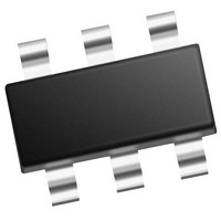
PIC10F322T-I/OT Microchip Technology, PIC10F322T-I/OT Datasheet - Page 203

PIC10F322T-I/OT
Manufacturer Part Number
PIC10F322T-I/OT
Description
896 B Flash, 64 B RAM, 4 I/O, 8bit ADC, PWM, CLC, DDS, CWG, TEMP Indicator, 2.3V
Manufacturer
Microchip Technology
Datasheet
1.PIC10F320-IOT.pdf
(210 pages)
Specifications of PIC10F322T-I/OT
Core
RISC
Processor Series
PIC10F
Data Bus Width
8 bit
Maximum Clock Frequency
31 KHz
Program Memory Size
512 B
Data Ram Size
64 B
Number Of Programmable I/os
4
Number Of Timers
2
Operating Temperature Range
- 40 C to + 85 C
Package / Case
SOT-23-6
Mounting Style
SMD/SMT
Maximum Operating Temperature
+ 85 C
Program Memory Type
Flash
Lead Free Status / Rohs Status
Details
Available stocks
Company
Part Number
Manufacturer
Quantity
Price
Company:
Part Number:
PIC10F322T-I/OT
Manufacturer:
VISHAY
Quantity:
11 490
Part Number:
PIC10F322T-I/OT
Manufacturer:
MICROCHIP/微芯
Quantity:
20 000
INDEX
A
A/D
Absolute Maximum Ratings (PIC10(L)F320/322) ............. 169
AC Characteristics
ADC .................................................................................... 91
ADCON Register................................................................. 17
ADRES Register ................................................................. 97
ADRESH Register............................................................... 17
Analog-to-Digital Converter. See ADC
ANSELA Register ............................................................... 78
Assembler
B
Block Diagrams
BORCON Register .............................................................. 35
Brown-out Reset (BOR) ...................................................... 35
C
C Compilers
CCP1CON Register ............................................................ 17
CCPR1H Register ............................................................... 17
CLCxCON Register........................................................... 119
CLCxGLS0 Register ......................................................... 123
CLCxGLS1 Register ......................................................... 124
CLCxGLS2 Register ......................................................... 125
CLCxGLS3 Register ......................................................... 126
CLCxPOL Register ........................................................... 120
CLCxSEL0 Register .......................................................... 121
CLCxSEL1 Register .......................................................... 122
2011 Microchip Technology Inc.
Specifications............................................................ 184
Industrial and Extended (PIC10(L)F320/322) ........... 180
Load Conditions ........................................................ 179
Acquisition Requirements ........................................... 98
Associated registers.................................................. 100
Block Diagram............................................................. 91
Calculating Acquisition Time....................................... 98
Channel Selection....................................................... 92
Configuration............................................................... 92
Configuring Interrupt ................................................... 95
Conversion Clock........................................................ 92
Conversion Procedure ................................................ 95
Internal Sampling Switch (R
Interrupts..................................................................... 94
Operation .................................................................... 94
Operation During Sleep .............................................. 94
Port Configuration ....................................................... 92
Reference Voltage (V
Source Impedance...................................................... 98
MPASM Assembler................................................... 190
ADC ............................................................................ 91
ADC Transfer Function ............................................... 99
Analog Input Model ..................................................... 99
Clock Source............................................................... 27
Interrupt Logic ............................................................. 41
NCO .......................................................................... 130
On-Chip Reset Circuit ................................................. 33
PIC10(L)F320/322 ........................................................ 8
PWM ......................................................................... 107
Timer2....................................................................... 105
TMR0/WDT Prescaler............................................... 101
Voltage Reference ...................................................... 85
Timing and Characteristics ....................................... 182
MPLAB C18 .............................................................. 190
REF
)........................................... 92
SS
) Impedance................ 98
Preliminary
Clock Sources
Code Examples
Complementary Waveform Generator (CWG).................. 139
CONFIG Register ............................................................... 22
Customer Change Notification Service............................. 207
Customer Notification Service .......................................... 207
Customer Support............................................................. 207
CWG
CWGxCON0 Register....................................................... 149
CWGxCON1 Register....................................................... 150
CWGxCON2 Register....................................................... 151
CWGxDBF Register.......................................................... 152
CWGxDBR Register ......................................................... 152
D
Data Memory ...................................................................... 13
DC and AC Characteristics............................................... 187
DC Characteristics
Development Support ....................................................... 189
Device Configuration .......................................................... 21
Device Overview............................................................. 7, 53
E
EECON1 Register............................................................... 18
EEDATL Register ............................................................... 70
Effects of Reset
Electrical Specifications (PIC10(L)F320/322) ................... 169
Errata .................................................................................... 6
F
Firmware Instructions ....................................................... 159
Fixed Voltage Reference (FVR)
Flash Program Memory ...................................................... 57
FSR Register ...................................................................... 17
FVRCON (Fixed Voltage Reference Control) Register....... 86
G
General Purpose Register File ........................................... 13
External Modes........................................................... 31
Indirect Addressing..................................................... 19
Initializing PORTA ...................................................... 75
Saving Status and W Registers in RAM ..................... 45
Writing to Flash Program Memory.............................. 66
Auto-shutdown Control ............................................. 146
Clock Source ............................................................ 142
Output Control .......................................................... 142
Selectable Input Sources.......................................... 142
Extended and Industrial (PIC10(L)F320/322)........... 176
Industrial and Extended (PIC10(L)F320/322)........... 171
Code Protection.......................................................... 24
Configuration Word..................................................... 21
User ID ................................................................. 24, 25
PWM mode............................................................... 109
Associated Registers.................................................. 86
Associated Registers.................................................. 73
Configuration Word w/ Flash Program Memory ......... 73
Erasing ....................................................................... 61
Modifying .................................................................... 67
Write Verify ................................................................. 69
Writing ........................................................................ 63
PIC10(L)F320/322
EC ...................................................................... 31
DS41585A-page 203


