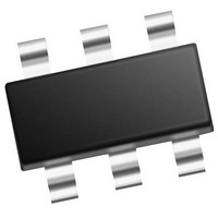
PIC10F322T-I/OT Microchip Technology, PIC10F322T-I/OT Datasheet - Page 205

PIC10F322T-I/OT
Manufacturer Part Number
PIC10F322T-I/OT
Description
896 B Flash, 64 B RAM, 4 I/O, 8bit ADC, PWM, CLC, DDS, CWG, TEMP Indicator, 2.3V
Manufacturer
Microchip Technology
Datasheet
1.PIC10F320-IOT.pdf
(210 pages)
Specifications of PIC10F322T-I/OT
Core
RISC
Processor Series
PIC10F
Data Bus Width
8 bit
Maximum Clock Frequency
31 KHz
Program Memory Size
512 B
Data Ram Size
64 B
Number Of Programmable I/os
4
Number Of Timers
2
Operating Temperature Range
- 40 C to + 85 C
Package / Case
SOT-23-6
Mounting Style
SMD/SMT
Maximum Operating Temperature
+ 85 C
Program Memory Type
Flash
Lead Free Status / Rohs Status
Details
Available stocks
Company
Part Number
Manufacturer
Quantity
Price
Company:
Part Number:
PIC10F322T-I/OT
Manufacturer:
VISHAY
Quantity:
11 490
Part Number:
PIC10F322T-I/OT
Manufacturer:
MICROCHIP/微芯
Quantity:
20 000
PR2 Register....................................................................... 17
Prescaler
Program Memory ................................................................ 11
Programming, Device Instructions .................................... 159
Pulse Width Modulation (PWM) ........................................ 107
PWMxCON Register ......................................................... 111
PWMxDCH Register ......................................................... 112
PWMxDCL Register .......................................................... 112
R
Reader Response ............................................................. 208
Read-Modify-Write Operations ......................................... 159
Registers
2011 Microchip Technology Inc.
Shared WDT/Timer0 ................................................. 102
Map and Stack (PIC10(L)F320 ................................... 12
Associated registers w/ PWM ................................... 112
PWM Mode
PWM Period.............................................................. 108
Setup for PWM Operation using PWMx Pins............ 110
ADRES (ADC Result) ................................................. 97
ANSELA (PORTA Analog Select)............................... 78
BORCON Brown-out Reset Control)........................... 35
CLCxCON (CLCx Control) ........................................ 119
CLCxGL1 (Gate 2 Logic Select) ............................... 124
CLCxGLS0 (Gate 1 Logic Select) ............................. 123
CLCxGLS2 (Gate 3 Logic Select) ............................. 125
CLCxGLS3 (Gate 4 Logic Select) ............................. 126
CLCxPOL (Signal Polarity Control)........................... 120
CLCxSEL0 (Multiplexer Data 1 and 2 Select)........... 121
CLCxSEL1 (Multiplexer Data 3 and 4 Select)........... 122
Configuration Word ..................................................... 22
CWGxCON0 (CWG Control 0).................................. 149
CWGxCON1 (CWG Control 1).................................. 150
CWGxCON2 (CWG Control 1).................................. 151
CWGxDBF (CWGx Dead Band Falling Count) ......... 152
CWGxDBR (CWGx Dead Band Rising Count) ......... 152
EEDATL (EEPROM Data) .......................................... 70
FVRCON..................................................................... 86
INTCON (Interrupt Control)......................................... 46
IOCBP (Interrupt-on-Change Positive Edge) .............. 83
LATA (Data Latch PORTA)......................................... 78
NCOxACCH (NCOx Accumulator High Byte) ........... 136
NCOxACCL (NCOx Accumulator Low Byte)............. 136
NCOxACCU (NCOx Accumulator Upper Byte)......... 136
NCOxCLK (NCOx Clock Control) ............................. 135
NCOxCON (NCOx Control) ...................................... 135
NCOxINCH (NCOx Increment High Byte)................. 137
NCOxINCL (NCOx Increment Low Byte) .................. 137
OPTION_REG (Option) ............................................ 103
OSCCON (Oscillator Control) ..................................... 30
PCON (Power Control) ............................................... 39
PIE1 (Peripheral Interrupt Enable 1)........................... 47
PIR1 (Peripheral Interrupt Register 1) ........................ 48
PMADRL (Program Memory Address)........................ 71
PMCON1 (Program Memory Control 1)...................... 72
PMCON2 (Program Memory Control 2)...................... 73
PMDATH (Program Memory Data) ....................... 70, 71
Duty Cycle ........................................................ 108
Effects of Reset ................................................ 109
Example PWM Frequencies and
Example PWM Frequencies and
Operation in Sleep Mode .................................. 109
Setup for Operation using PWMx pins.............. 110
System Clock Frequency Changes .................. 109
Resolutions, 20 MHZ ................................ 109
Resolutions, 8 MHz................................... 109
Preliminary
Reset .................................................................................. 33
Resets ................................................................................ 33
Revision History................................................................ 201
S
Software Simulator (MPLAB SIM) .................................... 191
SPBRG Register................................................................. 17
Special Function Registers ................................................. 13
Special Function Registers (SFRs)..................................... 17
STATUS Register ............................................................... 15
T
T2CON Register ......................................................... 17, 106
Temperature Indicator Module............................................ 89
Thermal Considerations (PIC10(L)F320/322)................... 178
Timer0 .............................................................................. 101
Timer1 .............................................................................. 105
Timer2
Timers
Timing Diagrams
Timing Parameter Symbology .......................................... 179
TMR0 Register.................................................................... 17
TMR2 Register.................................................................... 17
TRISA Register................................................................... 77
V
V
W
Wake-up Using Interrupts ................................................... 52
Watchdog Timer (WDT)...................................................... 36
WDTCON Register ............................................................. 55
Write Protection .................................................................. 24
REF
PORTA ....................................................................... 77
PWMxCON (PWM Control) ...................................... 111
PWMxDCH (PWM Control) ...................................... 112
PWMxDCL (PWM Control) ....................................... 112
Special Function Registers......................................... 13
Special Function, Summary........................................ 17
STATUS ..................................................................... 15
T2CON ..................................................................... 106
TRISA (Tri-State PORTA) .......................................... 77
WDTCON (Watchdog Timer Control) ......................... 55
Associated Registers.................................................. 39
Configuration Word w/ Clock Resets.......................... 39
Associated Registers................................................ 103
Interrupt .................................................................... 103
Operation.................................................................. 101
Specifications ........................................................... 183
Associated registers ................................................. 106
Timer2
A/D Conversion ........................................................ 185
A/D Conversion (Sleep Mode).................................. 185
Brown-out Reset (BOR)............................................ 182
Brown-out Reset Situations ........................................ 35
CLKR and I/O ........................................................... 181
Clock Timing............................................................. 180
INT Pin Interrupt ......................................................... 44
Reset Start-up Sequence ........................................... 37
Timer0 External Clock .............................................. 183
Wake-up from Interrupt............................................... 52
. S
Associated Registers.................................................. 56
Configuration Word w/ Watchdog Timer..................... 56
Modes......................................................................... 54
Specifications ........................................................... 183
EE
PIC10(L)F320/322
T2CON ............................................................. 106
ADC Reference Voltage
DS41585A-page 205


