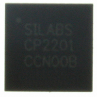
CP2201-GM Silicon Laboratories Inc, CP2201-GM Datasheet - Page 48

CP2201-GM
Manufacturer Part Number
CP2201-GM
Description
IC ETH CTRLR SNGL-CHIP 28QFN
Manufacturer
Silicon Laboratories Inc
Specifications of CP2201-GM
Package / Case
48-TQFP, 48-VQFP
Controller Type
Ethernet Controller, MAC/10Base-T
Interface
Parallel/Serial
Voltage - Supply
3.1 V ~ 3.6 V
Current - Supply
75mA
Operating Temperature
-40°C ~ 85°C
Mounting Type
Surface Mount
Ethernet Connection Type
1000BASE-T or 100BASE-T or 10BASE-T
Minimum Operating Temperature
- 40 C
Mounting Style
SMD/SMT
Product
Ethernet Controllers
Standard Supported
IEEE 802.3
Data Rate
10 Mbps or 100 Mbps or 1000 Mbps
Maximum Operating Temperature
+ 85 C
No. Of Ports
1
Ethernet Type
IEEE 802.3
Interface Type
Parallel
Supply Current
60mA
Supply Voltage Range
3.1V To 3.6V
Operating Temperature Range
-40°C To +85°C
Rohs Compliant
Yes
Lead Free Status / RoHS Status
Lead free / RoHS Compliant
For Use With
336-1326 - KIT REF DESIGN PWR OVER ETHERNET336-1316 - KIT EVAL FOR CP2201 ETH CTRLR
Lead Free Status / Rohs Status
Lead free / RoHS Compliant
Other names
336-1313
Available stocks
Company
Part Number
Manufacturer
Quantity
Price
Company:
Part Number:
CP2201-GM
Manufacturer:
SiliconL
Quantity:
48
Part Number:
CP2201-GMR
Manufacturer:
SILICON LABS/芯科
Quantity:
20 000
CP2200/1
11.2. Transmitting a Packet
Once reset initialization is complete (See ), the CP2200/1 is ready to transmit Ethernet packets. The following
procedure can be used to transmit a packet:
Note: Step 4 may be skipped if Step 3 is always performed.
11.3. Overriding Transmit Configuration Options
The global transmit configuration options are set in the MAC registers. The transmit interface allows the host
processor to customize packet transmission on a per-packet basis by overriding the global MAC settings. The
following options can be overridden by the transmit interface:
11.4. Transmit Buffer and AutoWrite Interface
The transmit buffer provides the AutoWrite interface to efficiently load the buffer with an entire packet. The interface
consists of three registers: TXSTART, TXEND, and TXAUTOWR. The TXSTART register points to the address of
the next available byte and can be reset to the first byte of the buffer. TXEND points to the last byte added to the
buffer. TXAUTOWR is the data register. Each write to TXAUTOWR sets TXEND to the address of the byte written
and increments TXSTART. After the packet is loaded into the buffer, TXSTART is reset to 0x0000 to mark the
starting point of the packet. TXEND will continue to point to the last byte in the packet.
Note: The AutoWrite Interface cannot be used following an aborted packet. This only applies if the device is in half-duplex
48
Short Frame Padding—When enabled, ensures that no frame smaller than 64 bytes is transmitted. The frame
size does not include the 8 byte preamble; however, the 4-byte CRC field is included.
CRC Generation—When enabled, a 32-bit CRC will be calculated and appended to the Ethernet frame.
Pause packet transmission (Full Duplex Mode)—When enabled, an Ethernet PAUSE packet with a pause value
of TXPAUSEH:TXPAUSEL is transmitted. The pause value is in units of 512 bit times (51.2 µs).
Application of Back Pressure (Half Duplex Mode).
Switching between Half/Full Duplex Modes. Note: This setting does not affect the physical layer.
Step 1: Wait for the previous packet to complete (TXBUSY == 0x00). The worst case time to transmit a
Step 2: Set the TXSTARTH:TXSTARTL transmit buffer pointer to 0x0000.
Step 3: If the last packet was aborted ((TXSTA3 & 0xF8) != 0x00), then this packet must be loaded into the
Step 4: If the last packet was successfully transmitted ((TXSTA2 & 0x80) == 0x80), then this packet may be
Step 5: Set the TXSTARTH:TXSTARTL transmit buffer pointer back to 0x0000.
Step 6: Write a ‘1’ to the TXGO bit (TXCN.0) to begin transmission.
mode.
packet is 500 ms in half-duplex mode with exponential backoff.
transmit buffer using the Random Memory Access Method:
a. Set RAMADDRH:RAMADDRL to 0x0000.
b. Write the first data byte to RAMTXDATA.
c. Increment RAMADDRH:RAMADDRL.
d. Write another data byte to RAMTXDATA.
e. Repeat steps c and d until the entire packet is loaded.
f. Pad small packets to at least 64 bytes.
g. Set TXENDH:TXENDL to the address of the last byte added. This value must be greater than or
loaded into the transmit buffer using the AutoWrite Interface:
a. Write all data bytes to the TXAUTOWR register, one byte at time.
b. If the MAC is in half-duplex mode, pad small packets to at least 64 bytes.
equal to 0x0040.
Rev. 1.0


