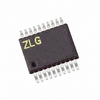
Z8F042AHH020EG Zilog, Z8F042AHH020EG Datasheet - Page 132

Z8F042AHH020EG
Manufacturer Part Number
Z8F042AHH020EG
Description
IC ENCORE XP MCU FLASH 4K 20SSOP
Manufacturer
Zilog
Series
Encore!® XP®r
Datasheet
1.Z8F08200100KIT.pdf
(264 pages)
Specifications of Z8F042AHH020EG
Core Processor
Z8
Core Size
8-Bit
Speed
20MHz
Connectivity
IrDA, UART/USART
Peripherals
Brown-out Detect/Reset, LED, LVD, POR, PWM, Temp Sensor, WDT
Number Of I /o
17
Program Memory Size
4KB (4K x 8)
Program Memory Type
FLASH
Eeprom Size
128 x 8
Ram Size
1K x 8
Voltage - Supply (vcc/vdd)
2.7 V ~ 3.6 V
Data Converters
A/D 7x10b
Oscillator Type
Internal
Operating Temperature
-40°C ~ 105°C
Package / Case
20-SSOP
Lead Free Status / RoHS Status
Lead free / RoHS Compliant
Other names
269-4156
Z8F042AHH020EG
Z8F042AHH020EG
- Current page: 132 of 264
- Download datasheet (6Mb)
PS022517-0508
Error Detection
SPI Interrupts
NUMBITS field in the SPIMODE Register must be set to be consistent with the other
SPI devices. The STR bit in the SPICTL Register can be used if desired to force a
“startup” interrupt. The BIRQ bit in the SPICTL Register and the SSV bit in the
SPIMODE Register is not used in SLAVE mode. The SPI Baud Rate Generator is not used
in SLAVE mode so the SPIBRH and SPIBRL Registers need not be initialized.
If the slave has data to send to the master, the data must be written to the SPIDAT
Register before the transaction starts (first edge of SCK when SS is asserted). If the
SPIDAT Register is not written prior to the slave transaction, the MISO pin outputs
whatever value is currently in the SPIDAT Register.
Due to the delay resulting from synchronization of the SPI input signals to the internal
system clock, the maximum SPICLK baud rate that can be supported in SLAVE mode is
the system clock frequency (XIN) divided by 8. This rate is controlled by the SPI Master.
The SPI contains error detection logic to support SPI communication protocols and recog-
nize when communication errors have occurred. The SPI Status Register indicates when a
data transmission error has been detected.
Overrun (Write Collision)
An overrun error (write collision) indicates a write to the SPI Data Register was attempted
while a data transfer is in progress (in either Master or Slave modes). An overrun sets the
OVR bit in the SPI Status Register to 1. Writing a 1 to OVR clears this error flag. The data
register is not altered when a write occurs while data transfer is in progress.
Mode Fault (Multi-Master Collision)
A mode fault indicates when more than one Master is trying to communicate at the same
time (a multi-master collision). The mode fault is detected when the enabled Master’s SS
pin is asserted. A mode fault sets the COL bit in the SPI Status Register to 1. Writing a 1 to
COL clears this error Flag.
SLAVE Mode Abort
In SLAVE mode, if the SS pin deasserts before all bits in a character have been
transferred, the transaction aborts. When this condition occurs the
SPISTAT Register as well as the
time SS asserts, the MISO pin outputs SPIDAT[7], regardless of where the previous
transaction left off. Writing a 1 to ABT clears this error flag.
When SPI interrupts are enabled, the SPI generates an interrupt after character transmis-
sion/reception completes in both Master and Slave modes. A character is defined to be 1
through 8 bits by the NUMBITS field in the SPI Mode Register. In SLAVE mode it is not
IRQ
bit (indicating the transaction is complete). The next
Z8 Encore! XP
Product Specification
ABT
Serial Peripheral Interface
bit is set in the
®
F0822 Series
119
Related parts for Z8F042AHH020EG
Image
Part Number
Description
Manufacturer
Datasheet
Request
R

Part Number:
Description:
Communication Controllers, ZILOG INTELLIGENT PERIPHERAL CONTROLLER (ZIP)
Manufacturer:
Zilog, Inc.
Datasheet:

Part Number:
Description:
KIT DEV FOR Z8 ENCORE 16K TO 64K
Manufacturer:
Zilog
Datasheet:

Part Number:
Description:
KIT DEV Z8 ENCORE XP 28-PIN
Manufacturer:
Zilog
Datasheet:

Part Number:
Description:
DEV KIT FOR Z8 ENCORE 8K/4K
Manufacturer:
Zilog
Datasheet:

Part Number:
Description:
KIT DEV Z8 ENCORE XP 28-PIN
Manufacturer:
Zilog
Datasheet:

Part Number:
Description:
DEV KIT FOR Z8 ENCORE 4K TO 8K
Manufacturer:
Zilog
Datasheet:

Part Number:
Description:
CMOS Z8 microcontroller. ROM 16 Kbytes, RAM 256 bytes, speed 16 MHz, 32 lines I/O, 3.0V to 5.5V
Manufacturer:
Zilog, Inc.
Datasheet:

Part Number:
Description:
Low-cost microcontroller. 512 bytes ROM, 61 bytes RAM, 8 MHz
Manufacturer:
Zilog, Inc.
Datasheet:

Part Number:
Description:
Z8 4K OTP Microcontroller
Manufacturer:
Zilog, Inc.
Datasheet:

Part Number:
Description:
CMOS SUPER8 ROMLESS MCU
Manufacturer:
Zilog, Inc.
Datasheet:

Part Number:
Description:
SL1866 CMOSZ8 OTP Microcontroller
Manufacturer:
Zilog, Inc.
Datasheet:

Part Number:
Description:
SL1866 CMOSZ8 OTP Microcontroller
Manufacturer:
Zilog, Inc.
Datasheet:

Part Number:
Description:
OTP (KB) = 1, RAM = 125, Speed = 12, I/O = 14, 8-bit Timers = 2, Comm Interfaces Other Features = Por, LV Protect, Voltage = 4.5-5.5V
Manufacturer:
Zilog, Inc.
Datasheet:

Part Number:
Description:
Manufacturer:
Zilog, Inc.
Datasheet:


