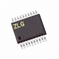
Z8F042AHH020EG Zilog, Z8F042AHH020EG Datasheet - Page 174

Z8F042AHH020EG
Manufacturer Part Number
Z8F042AHH020EG
Description
IC ENCORE XP MCU FLASH 4K 20SSOP
Manufacturer
Zilog
Series
Encore!® XP®r
Datasheet
1.Z8F08200100KIT.pdf
(264 pages)
Specifications of Z8F042AHH020EG
Core Processor
Z8
Core Size
8-Bit
Speed
20MHz
Connectivity
IrDA, UART/USART
Peripherals
Brown-out Detect/Reset, LED, LVD, POR, PWM, Temp Sensor, WDT
Number Of I /o
17
Program Memory Size
4KB (4K x 8)
Program Memory Type
FLASH
Eeprom Size
128 x 8
Ram Size
1K x 8
Voltage - Supply (vcc/vdd)
2.7 V ~ 3.6 V
Data Converters
A/D 7x10b
Oscillator Type
Internal
Operating Temperature
-40°C ~ 105°C
Package / Case
20-SSOP
Lead Free Status / RoHS Status
Lead free / RoHS Compliant
Other names
269-4156
Z8F042AHH020EG
Z8F042AHH020EG
- Current page: 174 of 264
- Download datasheet (6Mb)
Table 86. Flash Sector Protect Register (FPROT)
PS022517-0508
BITS
FIELD
RESET
R/W
ADDR
R/W1 = Register is accessible for Read operations. Register can be written to 1 only (using user code).
Flash Sector Protect Register
Flash Frequency High and Low Byte Registers
Caution:
SECT7
7
INFO_EN—Information Area Enable
0 = Information Area is not selected.
1 = Information Area is selected. The Information area is mapped into the
PAGE—Page Select
This 7-bit field selects the Flash memory page for Programming and Page Erase
operations. Flash Memory Address[15:9] = PAGE[6:0].
The Flash Sector Protect Register
programmed or erased from user code. The Flash Sector Protect Register shares its
Register File address with the Page Select Register. The Flash Sector Protect Register can
be accessed only after writing the Flash Control Register with
write bits in this register to 1 (bits cannot be cleared to 0 by user code).
SECTn—Sector Protect
0 = Sector n can be programmed or erased from user code.
1 = Sector n is protected and cannot be programmed or erased from user code.
The Flash Frequency High and Low Byte Registers
form a 16-bit value, FFREQ, to control timing for Flash program and erase operations.
The 16-bit Flash Frequency registers must be written with the system clock frequency in
kHz for Program and Erase operations. The Flash Frequency value is calculated using the
following equation:
User code can only write bits from 0 to 1.
FFREQ[15:0]
Flash Memory address space at addresses
Flash programming and erasure is not supported for system clock frequen-
cies below 20 kHz, above 20 MHz, or outside of the valid operating
SECT6
6
=
{
FFREQH[7:0],FFREQL[7:0]
SECT5
5
SECT4
(Table
4
R/W1
FF9H
86) protects Flash memory sectors from being
0
SECT3
FE00H
}
3
=
System Clock Frequency
----------------------------------------------------------------- -
(Table 87
through
Z8 Encore! XP
SECT2
2
1000
and
FFFFH
5EH
Product Specification
Table
. User code can only
SECT1
.
1
®
88) combine to
F0822 Series
Flash Memory
SECT0
0
161
Related parts for Z8F042AHH020EG
Image
Part Number
Description
Manufacturer
Datasheet
Request
R

Part Number:
Description:
Communication Controllers, ZILOG INTELLIGENT PERIPHERAL CONTROLLER (ZIP)
Manufacturer:
Zilog, Inc.
Datasheet:

Part Number:
Description:
KIT DEV FOR Z8 ENCORE 16K TO 64K
Manufacturer:
Zilog
Datasheet:

Part Number:
Description:
KIT DEV Z8 ENCORE XP 28-PIN
Manufacturer:
Zilog
Datasheet:

Part Number:
Description:
DEV KIT FOR Z8 ENCORE 8K/4K
Manufacturer:
Zilog
Datasheet:

Part Number:
Description:
KIT DEV Z8 ENCORE XP 28-PIN
Manufacturer:
Zilog
Datasheet:

Part Number:
Description:
DEV KIT FOR Z8 ENCORE 4K TO 8K
Manufacturer:
Zilog
Datasheet:

Part Number:
Description:
CMOS Z8 microcontroller. ROM 16 Kbytes, RAM 256 bytes, speed 16 MHz, 32 lines I/O, 3.0V to 5.5V
Manufacturer:
Zilog, Inc.
Datasheet:

Part Number:
Description:
Low-cost microcontroller. 512 bytes ROM, 61 bytes RAM, 8 MHz
Manufacturer:
Zilog, Inc.
Datasheet:

Part Number:
Description:
Z8 4K OTP Microcontroller
Manufacturer:
Zilog, Inc.
Datasheet:

Part Number:
Description:
CMOS SUPER8 ROMLESS MCU
Manufacturer:
Zilog, Inc.
Datasheet:

Part Number:
Description:
SL1866 CMOSZ8 OTP Microcontroller
Manufacturer:
Zilog, Inc.
Datasheet:

Part Number:
Description:
SL1866 CMOSZ8 OTP Microcontroller
Manufacturer:
Zilog, Inc.
Datasheet:

Part Number:
Description:
OTP (KB) = 1, RAM = 125, Speed = 12, I/O = 14, 8-bit Timers = 2, Comm Interfaces Other Features = Por, LV Protect, Voltage = 4.5-5.5V
Manufacturer:
Zilog, Inc.
Datasheet:

Part Number:
Description:
Manufacturer:
Zilog, Inc.
Datasheet:


