HD6417708SF60 Renesas Electronics America, HD6417708SF60 Datasheet - Page 166
HD6417708SF60
Manufacturer Part Number
HD6417708SF60
Description
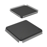
IC SUPERH MPU ROMLESS 144LQFP
Manufacturer
Renesas Electronics America
Series
SuperH® SH7700r
Datasheet
1.HD6417708SF60V.pdf
(635 pages)
Specifications of HD6417708SF60
Core Processor
SH-2
Core Size
32-Bit
Speed
60MHz
Connectivity
EBI/EMI, SCI, SmartCard
Peripherals
POR, WDT
Number Of I /o
8
Program Memory Type
ROMless
Voltage - Supply (vcc/vdd)
3 V ~ 3.6 V
Oscillator Type
External
Operating Temperature
-20°C ~ 75°C
Package / Case
144-LQFP
Lead Free Status / RoHS Status
Contains lead / RoHS non-compliant
Eeprom Size
-
Ram Size
-
Program Memory Size
-
Data Converters
-
Available stocks
Company
Part Number
Manufacturer
Quantity
Price
Company:

Part Number:
HD6417708SF60
Manufacturer:
HITACHI
Quantity:
2 400
Company:
Part Number:
HD6417708SF60
Manufacturer:
Renesas Electronics America
Quantity:
10 000
Company:
Part Number:
HD6417708SF60I
Manufacturer:
ACCMICRO
Quantity:
144
Company:
Part Number:
HD6417708SF60V
Manufacturer:
Renesas Electronics America
Quantity:
10 000
Part Number:
HD6417708SF60V
Manufacturer:
RENESAS/瑞萨
Quantity:
20 000


Table 8.4
Module
Interrupt controller
Break controller
Bus state controller
On-chip clock pulse generator
Timer unit
Realtime clock
The procedure for moving to standby mode is as follows:
1. Clear the TME bit in the WDT’s timer control register (WTCSR) to 0 to stop the WDT. Set the
2. When PLL circuit 1 is running in clock modes 3–6, clear the PSTBY and PLLEN bits in the
3. After the STBY bit in the STBCR register is set to 1, a SLEEP instruction is executed.
4. Standby mode is entered and the clocks within the chip are halted. The STATUS1 pin output
8.4.2
Standby mode is canceled by an interrupt (NMI, IRL, or on-chip supporting module) or a reset.
Canceling with an Interrupt: The on-chip WDT can be used for hot starts. When the chip detects
an NMI, IRL,
will be supplied to the entire chip and standby mode canceled after the time set in the WDT’s
timer control/status register has elapsed. The STATUS1 and STATUS0 pins both go low. Interrupt
handling then begins and a code indicating the interrupt source is set in the INTEVT register.
Interrupts are accepted during standby mode even when the BL bit in the SR register is 1.
Immediately after an interrupt is detected, the phase of the clock output of the CKIO pin may be
unstable, until the processor starts interrupt handling. (The canceling condition is that the
IRL3–IRL0 level is higher than the mask level in the I3–I0 bits in the SR register.)
Notes: 1. When the RTC is being used, standby mode can be canceled using IRL3–IRL0.
146
WDT’s timer counter (WTCNT) and the CKS2–CKS0 bits of the WTCSR register to
appropriate values to secure the specified oscillation settling time.
frequency control register (FRQCR) to 0 to stop PLL circuit 1.
goes low and the STATUS0 pin output goes high.
2. Standby mode can be canceled with an RTC or TMU (only when running on the RTC
Canceling Standby Mode
clock) interrupt.
Register States in Standby Mode
*1
or on-chip supporting module (except the interval timer)
Registers Initialized
—
—
—
—
TSTR register
—
Registers Retaining Data
All registers
All registers
All registers
All registers
Registers other than TSTR
All registers
*2
interrupt, the clock
Related parts for HD6417708SF60
Image
Part Number
Description
Manufacturer
Datasheet
Request
R

Part Number:
Description:
KIT STARTER FOR M16C/29
Manufacturer:
Renesas Electronics America
Datasheet:

Part Number:
Description:
KIT STARTER FOR R8C/2D
Manufacturer:
Renesas Electronics America
Datasheet:

Part Number:
Description:
R0K33062P STARTER KIT
Manufacturer:
Renesas Electronics America
Datasheet:

Part Number:
Description:
KIT STARTER FOR R8C/23 E8A
Manufacturer:
Renesas Electronics America
Datasheet:

Part Number:
Description:
KIT STARTER FOR R8C/25
Manufacturer:
Renesas Electronics America
Datasheet:

Part Number:
Description:
KIT STARTER H8S2456 SHARPE DSPLY
Manufacturer:
Renesas Electronics America
Datasheet:

Part Number:
Description:
KIT STARTER FOR R8C38C
Manufacturer:
Renesas Electronics America
Datasheet:

Part Number:
Description:
KIT STARTER FOR R8C35C
Manufacturer:
Renesas Electronics America
Datasheet:

Part Number:
Description:
KIT STARTER FOR R8CL3AC+LCD APPS
Manufacturer:
Renesas Electronics America
Datasheet:
Part Number:
Description:
KIT STARTER FOR RX610
Manufacturer:
Renesas Electronics America
Datasheet:

Part Number:
Description:
KIT STARTER FOR R32C/118
Manufacturer:
Renesas Electronics America
Datasheet:

Part Number:
Description:
KIT DEV RSK-R8C/26-29
Manufacturer:
Renesas Electronics America
Datasheet:

Part Number:
Description:
KIT STARTER FOR SH7124
Manufacturer:
Renesas Electronics America
Datasheet:

Part Number:
Description:
KIT STARTER FOR H8SX/1622
Manufacturer:
Renesas Electronics America
Datasheet:

Part Number:
Description:
KIT DEV FOR SH7203
Manufacturer:
Renesas Electronics America
Datasheet: