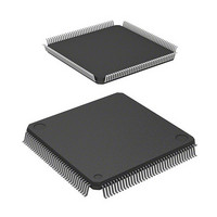
HD6417708SF60 Renesas Electronics America, HD6417708SF60 Datasheet - Page 392

HD6417708SF60
Manufacturer Part Number
HD6417708SF60
Description
IC SUPERH MPU ROMLESS 144LQFP
Manufacturer
Renesas Electronics America
Series
SuperH® SH7700r
Datasheet
1.HD6417708SF60V.pdf
(635 pages)
Specifications of HD6417708SF60
Core Processor
SH-2
Core Size
32-Bit
Speed
60MHz
Connectivity
EBI/EMI, SCI, SmartCard
Peripherals
POR, WDT
Number Of I /o
8
Program Memory Type
ROMless
Voltage - Supply (vcc/vdd)
3 V ~ 3.6 V
Oscillator Type
External
Operating Temperature
-20°C ~ 75°C
Package / Case
144-LQFP
Lead Free Status / RoHS Status
Contains lead / RoHS non-compliant
Eeprom Size
-
Ram Size
-
Program Memory Size
-
Data Converters
-
Available stocks
Company
Part Number
Manufacturer
Quantity
Price
Company:
Part Number:
HD6417708SF60
Manufacturer:
HITACHI
Quantity:
2 400
Company:
Part Number:
HD6417708SF60
Manufacturer:
Renesas Electronics America
Quantity:
10 000
Company:
Part Number:
HD6417708SF60I
Manufacturer:
ACCMICRO
Quantity:
144
Company:
Part Number:
HD6417708SF60V
Manufacturer:
Renesas Electronics America
Quantity:
10 000
Part Number:
HD6417708SF60V
Manufacturer:
RENESAS/瑞萨
Quantity:
20 000
- Current page: 392 of 635
- Download datasheet (3Mb)
Figure 13.6 shows an example of SCI transmit operation in asynchronous mode.
Receiving Serial Data (Asynchronous Mode): Figure 13.7 shows a sample flowchart for
receiving serial data. The procedure for receiving serial data after enabling the SCI for reception
is:
1. Receive error handling and break detection: If a receive error occurs, read the ORER, PER and
2. SCI status check and receive-data read: Read the serial status register (SCSSR), check that
3. To continue receiving serial data: Read the RDRF and SCRDR bits and clear RDRF to 0
372
Figure 13.6 SCI Transmit Operation in Asynchronous Mode (Example: 8-Bit Data with
FER bits in SCSSR to identify the error. After executing the necessary error handling, clear
ORER, PER and FER all to 0. Receiving cannot resume if ORER, PER or FER remain set to 1.
When a framing error occurs, the RxD pin can be read to detect the break state.
RDRF is set to 1, then read receive data from the receive data register (SCRDR) and clear
RDRF to 0. The RXI interrupt can also be used to determine if the RDRF bit has changed from
0 to 1.
before the stop bit of the current frame is received.
TXI interrupt
TDRE
TEND
Serial
request
data
1
Start
bit
0
and clears TDRE
data to SCTDR
handler writes
TXI interrupt
D
bit to 0
0
D
1 frame
1
Data
Parity and One Stop Bit)
D
7
TXI interrupt
Parity
request
bit
0/1
Stop
bit
1
Start
bit
0
D
0
D
1
Data
D
7
Parity
bit
TEI interrupt
0/1
request
Stop
bit
1
(mark)
state
Idle
1
Related parts for HD6417708SF60
Image
Part Number
Description
Manufacturer
Datasheet
Request
R

Part Number:
Description:
KIT STARTER FOR M16C/29
Manufacturer:
Renesas Electronics America
Datasheet:

Part Number:
Description:
KIT STARTER FOR R8C/2D
Manufacturer:
Renesas Electronics America
Datasheet:

Part Number:
Description:
R0K33062P STARTER KIT
Manufacturer:
Renesas Electronics America
Datasheet:

Part Number:
Description:
KIT STARTER FOR R8C/23 E8A
Manufacturer:
Renesas Electronics America
Datasheet:

Part Number:
Description:
KIT STARTER FOR R8C/25
Manufacturer:
Renesas Electronics America
Datasheet:

Part Number:
Description:
KIT STARTER H8S2456 SHARPE DSPLY
Manufacturer:
Renesas Electronics America
Datasheet:

Part Number:
Description:
KIT STARTER FOR R8C38C
Manufacturer:
Renesas Electronics America
Datasheet:

Part Number:
Description:
KIT STARTER FOR R8C35C
Manufacturer:
Renesas Electronics America
Datasheet:

Part Number:
Description:
KIT STARTER FOR R8CL3AC+LCD APPS
Manufacturer:
Renesas Electronics America
Datasheet:

Part Number:
Description:
KIT STARTER FOR RX610
Manufacturer:
Renesas Electronics America
Datasheet:

Part Number:
Description:
KIT STARTER FOR R32C/118
Manufacturer:
Renesas Electronics America
Datasheet:

Part Number:
Description:
KIT DEV RSK-R8C/26-29
Manufacturer:
Renesas Electronics America
Datasheet:

Part Number:
Description:
KIT STARTER FOR SH7124
Manufacturer:
Renesas Electronics America
Datasheet:

Part Number:
Description:
KIT STARTER FOR H8SX/1622
Manufacturer:
Renesas Electronics America
Datasheet:

Part Number:
Description:
KIT DEV FOR SH7203
Manufacturer:
Renesas Electronics America
Datasheet:


