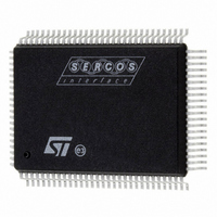
ST92F150JDV1QC STMicroelectronics, ST92F150JDV1QC Datasheet - Page 191

ST92F150JDV1QC
Manufacturer Part Number
ST92F150JDV1QC
Description
IC MCU 128K FLASH 100-PQFP
Manufacturer
STMicroelectronics
Series
ST9r
Datasheet
1.ST92F150CV1TB.pdf
(429 pages)
Specifications of ST92F150JDV1QC
Core Processor
ST9
Core Size
8/16-Bit
Speed
24MHz
Connectivity
CAN, I²C, LIN, SCI, SPI
Peripherals
DMA, LVD, POR, PWM, WDT
Number Of I /o
77
Program Memory Size
128KB (128K x 8)
Program Memory Type
FLASH
Eeprom Size
1K x 8
Ram Size
6K x 8
Voltage - Supply (vcc/vdd)
4.5 V ~ 5.5 V
Data Converters
A/D 16x10b
Oscillator Type
Internal
Operating Temperature
-40°C ~ 125°C
Package / Case
100-QFP
Processor Series
ST92F15x
Core
ST9
Data Bus Width
8 bit, 16 bit
Data Ram Size
6 KB
Interface Type
CAN, I2C, SCI, SPI
Maximum Clock Frequency
24 MHz
Number Of Programmable I/os
80
Number Of Timers
5 x 16 bit
Operating Supply Voltage
4.5 V to 5.5 V
Maximum Operating Temperature
+ 105 C
Mounting Style
SMD/SMT
Development Tools By Supplier
ST92F150-EPB
Minimum Operating Temperature
- 40 C
On-chip Adc
16 bit x 10 bit
Case
QFP
Lead Free Status / RoHS Status
Lead free / RoHS Compliant
Other names
497-2137
Available stocks
Company
Part Number
Manufacturer
Quantity
Price
- Current page: 191 of 429
- Download datasheet (8Mb)
MULTIFUNCTION TIMER (Cont’d)
10.4.2.8 Free Running Mode
The timer counts continuously (in Up or Down
mode) and the counter value simply overflows or
underflows through FFFFh or zero; there is no End
Of Count condition as such, and no reloading
takes place. This mode is automatically selected
either in Bi-capture mode or by setting register
REG0R for a Capture function (Continuous mode
must also be set). In Autoclear mode, free running
operation can be selected, with the possibility of
choosing a maximum count value less than 2
before overflow or underflow (see Autoclear
mode).
10.4.2.9 Monitor Mode
When the RM1 bit in TMR is reset, and the timer is
not in Bi-value mode, REG1R acts as a monitor,
duplicating the current up or down counter con-
tents, thus allowing the counter to be read “on the
fly”.
10.4.2.10 Autoclear Mode
A clear command forces the counter either to
0000h or to FFFFh, depending on whether up-
counting or downcounting is selected. The counter
reset may be obtained either directly, through the
CCL bit in TCR, or by entering the Autoclear
Mode, through the CCP0 and CCMP0 bits in TCR.
Every capture performed on REG0R (if CCP0 is
set), or every successful compare performed by
CMP0R (if CCMP0 is set), clears the counter and
reloads the prescaler.
16
The Clear On Capture mode allows direct meas-
urement of delta time between successive cap-
tures on REG0R, while the Clear On Compare
mode allows free running with the possibility of
choosing a maximum count value before overflow
or underflow which is less than 2
ning Mode).
10.4.2.11 Bi-value Mode
Depending on the value of the RM0 bit in TMR, the
Bi-load Mode (RM0 reset) or the Bi-capture Mode
(RM0 set) can be selected as illustrated in
38
Table 38. Bi-value Modes
A) Biload Mode
The Bi-load Mode is entered by selecting the Bi-
value Mode (BM set in TMR) and programming
REG0R as a reload register (RM0 reset in TMR).
At any End Of Count, counter reloading is per-
formed alternately from REG0R and REG1R, (a
low level for BM bit always sets REG0R as the cur-
rent register, so that, after a Low to High transition
of BM bit, the first reload is always from REG0R).
below:
RM0
0
1
TMR bits
MULTIFUNCTION TIMER (MFT)
RM1
X
X
BM
1
1
Operating Modes
Bi-Capture Mode
16
Bi-Load mode
(see Free Run-
Timer
191/429
Figure
9
Related parts for ST92F150JDV1QC
Image
Part Number
Description
Manufacturer
Datasheet
Request
R

Part Number:
Description:
BOARD PROGRAM FOR ST92F150 MCU
Manufacturer:
STMicroelectronics
Datasheet:

Part Number:
Description:
BOARD EVALUATION FOR ST9 SERIES
Manufacturer:
STMicroelectronics
Datasheet:

Part Number:
Description:
BOARD EMULATOR FOR ST9 SERIES
Manufacturer:
STMicroelectronics
Datasheet:

Part Number:
Description:
MCU, MPU & DSP Development Tools ST9 Dedication Board
Manufacturer:
STMicroelectronics
Datasheet:

Part Number:
Description:
STMicroelectronics [RIPPLE-CARRY BINARY COUNTER/DIVIDERS]
Manufacturer:
STMicroelectronics
Datasheet:

Part Number:
Description:
STMicroelectronics [LIQUID-CRYSTAL DISPLAY DRIVERS]
Manufacturer:
STMicroelectronics
Datasheet:

Part Number:
Description:
BOARD EVAL FOR MEMS SENSORS
Manufacturer:
STMicroelectronics
Datasheet:

Part Number:
Description:
NPN TRANSISTOR POWER MODULE
Manufacturer:
STMicroelectronics
Datasheet:

Part Number:
Description:
TURBOSWITCH ULTRA-FAST HIGH VOLTAGE DIODE
Manufacturer:
STMicroelectronics
Datasheet:

Part Number:
Description:
Manufacturer:
STMicroelectronics
Datasheet:

Part Number:
Description:
DIODE / SCR MODULE
Manufacturer:
STMicroelectronics
Datasheet:

Part Number:
Description:
DIODE / SCR MODULE
Manufacturer:
STMicroelectronics
Datasheet:


