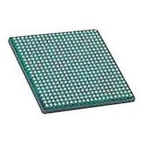
LFXP2-30E-5FN484C LATTICE SEMICONDUCTOR, LFXP2-30E-5FN484C Datasheet - Page 42

LFXP2-30E-5FN484C
Manufacturer Part Number
LFXP2-30E-5FN484C
Description
IC, LATTICEXP2 FPGA, 435MHZ, FPBGA-484
Manufacturer
LATTICE SEMICONDUCTOR
Series
LatticeXP2r
Datasheet
1.LFXP2-5E-5TN144C.pdf
(93 pages)
Specifications of LFXP2-30E-5FN484C
No. Of Logic Blocks
29000
No. Of Macrocells
14500
Family Type
LatticeXP2
No. Of Speed Grades
5
No. Of I/o's
363
Clock Management
PLL
Total Ram Bits
387Kbit
Lead Free Status / RoHS Status
Lead free / RoHS Compliant
Available stocks
Company
Part Number
Manufacturer
Quantity
Price
Company:
Part Number:
LFXP2-30E-5FN484C
Manufacturer:
Lattice Semiconductor Corporation
Quantity:
10 000
Lattice Semiconductor
1. Unlocked
2. Key Locked – Presenting the key through the programming interface allows the device to be unlocked.
3. Permanently Locked – The device is permanently locked.
To further complement the security of the device a One Time Programmable (OTP) mode is available. Once the
device is set in this mode it is not possible to erase or re-program the Flash portion of the device.
Serial TAG Memory
LatticeXP2 devices offer 0.6 to 3.3kbits of Flash memory in the form of Serial TAG memory. The TAG memory is an
area of the on-chip Flash that can be used for non-volatile storage including electronic ID codes, version codes,
date stamps, asset IDs and calibration settings. A block diagram of the TAG memory is shown in Figure 2-34. The
TAG memory is accessed in the same way as external SPI Flash and it can be read or programmed either through
JTAG, an external Slave SPI Port, or directly from FPGA logic. To read the TAG memory, a start address is speci-
fied and the entire TAG memory contents are read sequentially in a first-in-first-out manner. The TAG memory is
independent of the Flash used for device configuration and given its use for general-purpose storage functions is
always accessible regardless of the device security settings. For more information, see TN1137, LatticeXP2 Mem-
ory Usage Guide, and TN1141, LatticeXP2 sysCONFIG Usage Guide.
Figure 2-34. Serial TAG Memory Diagram
Live Update Technology
Many applications require field updates of the FPGA. LatticeXP2 devices provide three features that enable this
configuration to be done in a secure and failsafe manner while minimizing impact on system operation.
1. Decryption Support
2. TransFR (Transparent Field Reconfiguration)
3. Dual Boot Image Support
LatticeXP2 devices provide on-chip, non-volatile key storage to support decryption of a 128-bit AES encrypted
bitstream, securing designs and deterring design piracy.
TransFR I/O (TFR) is a unique Lattice technology that allows users to update their logic in the field without
interrupting system operation using a single ispVM command. TransFR I/O allows I/O states to be frozen dur-
ing device configuration. This allows the device to be field updated with a minimum of system disruption and
downtime. For more information please see TN1143, LatticeXP2 TransFR I/O.
Dual boot images are supported for applications requiring reliable remote updates of configuration data for the
system FPGA. After the system is running with a basic configuration, a new boot image can be downloaded
remotely and stored in a separate location in the configuration storage device. Any time after the update the
LatticeXP2 can be re-booted from this new configuration file. If there is a problem such as corrupt data during
download or incorrect version number with this new boot image, the LatticeXP2 device can revert back to the
External Slave
SPI Port
JTAG
FPGA Logic
Sequential
Address
Counter
TDI
Flash Memory Array
Data Shift Register
2-39
Flash
LatticeXP2 Family Data Sheet
TDO
External Slave
SPI Port
JTAG
FPGA Logic
Architecture


