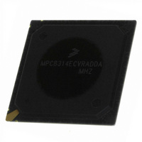
MPC8314ECVRADDA Freescale Semiconductor, MPC8314ECVRADDA Datasheet - Page 7

MPC8314ECVRADDA
Manufacturer Part Number
MPC8314ECVRADDA
Description
MPU POWERQUICC II PRO 620-PBGA
Manufacturer
Freescale Semiconductor
Datasheet
1.MPC8314VRADDA.pdf
(106 pages)
Specifications of MPC8314ECVRADDA
Processor Type
MPC83xx PowerQUICC II Pro 32-Bit
Speed
266MHz
Voltage
1V
Mounting Type
Surface Mount
Package / Case
620-PBGA
Processor Series
MPC8xxx
Core
e300
Data Bus Width
32 bit
Maximum Clock Frequency
50 MHz
Maximum Operating Temperature
+ 105 C
Mounting Style
SMD/SMT
Minimum Operating Temperature
- 40 C
Lead Free Status / RoHS Status
Lead free / RoHS Compliant
Features
-
Lead Free Status / Rohs Status
Lead free / RoHS Compliant
Available stocks
Company
Part Number
Manufacturer
Quantity
Price
Company:
Part Number:
MPC8314ECVRADDA
Manufacturer:
Freescale Semiconductor
Quantity:
135
Company:
Part Number:
MPC8314ECVRADDA
Manufacturer:
Freescale Semiconductor
Quantity:
10 000
There is one I
for expansion and system development.
The DUART supports full-duplex operation and is compatible with the PC16450 and PC16550
programming models. 16-byte FIFOs are supported for both the transmitter and the receiver.
The enhanced local bus controller (eLBC) port allows connections with a wide variety of external DSPs
and ASICs. Three separate state machines share the same external pins and can be programmed separately
to access different types of devices. The general-purpose chip select machine (GPCM) controls accesses
to asynchronous devices using a simple handshake protocol. The three user programmable machines
(UPMs) can be programmed to interface to synchronous devices or custom ASIC interfaces. Each chip
select can be configured so that the associated chip interface can be controlled by the GPCM or UPM
controller. Both may exist in the same system. The local bus can operate at up to 66 MHz.
The system timers include the following features: periodic interrupt timer, real time clock, software
watchdog timer, and two general-purpose timer blocks.
3
This section provides the AC and DC electrical specifications and thermal characteristics for the
MPC8314E, which is currently targeted to these specifications. Some of these specifications are
independent of the I/O cell, but they are included for complete reference. These are not purely I/O buffer
design specifications.
3.1
This section covers the ratings, conditions, and other characteristics.
3.1.1
Table 1
Freescale Semiconductor
Core supply voltage
PLL supply voltage
DDR1 DRAM I/O supply voltage
DDR2 DRAM I/O supply voltage
PCI, local bus, DUART, system control and power
management, I
JTAG I/O voltage
USB, and eTSEC I/O voltage
•
•
Misaligned transfer capability for source/destination address
Supports external DREQ, DACK and DONE signals
Electrical Characteristics
provides the absolute maximum ratings.
Overall DC Electrical Characteristics
Absolute Maximum Ratings
2
2
C, Ethernet management, 1588 timer and
C controller. This synchronous, multi-master buses can be connected to additional devices
MPC8314E PowerQUICC
Characteristic
Table 1. Absolute Maximum Ratings
™
II Pro Processor Hardware Specifications, Rev. 0
Symbol
GVDD
GVDD
NVDD
AVDD
LVDD
VDD
1
–0.3 to 2.75 or
–0.3 to 1.26
–0.3 to 1.26
Max Value
–0.3 to 2.7
–0.3 to 1.9
–0.3 to 3.6
–0.3 to 3.6
Electrical Characteristics
Unit
V
V
V
V
V
V
Notes
6, 8
—
—
—
—
7
7


