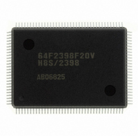
DF2398F20V Renesas Electronics America, DF2398F20V Datasheet - Page 18

DF2398F20V
Manufacturer Part Number
DF2398F20V
Description
IC H8S/2300 MCU FLASH 128QFP
Manufacturer
Renesas Electronics America
Series
H8® H8S/2300r
Specifications of DF2398F20V
Core Processor
H8S/2000
Core Size
16-Bit
Speed
20MHz
Connectivity
SCI, SmartCard
Peripherals
DMA, POR, PWM, WDT
Number Of I /o
87
Program Memory Size
256KB (256K x 8)
Program Memory Type
FLASH
Ram Size
8K x 8
Voltage - Supply (vcc/vdd)
4.5 V ~ 5.5 V
Data Converters
A/D 8x10b; D/A 2x8b
Oscillator Type
Internal
Operating Temperature
-20°C ~ 75°C
Package / Case
128-QFP
For Use With
YR0K42378FC000BA - KIT EVAL FOR H8S/2378
Lead Free Status / RoHS Status
Lead free / RoHS Compliant
Eeprom Size
-
Available stocks
Company
Part Number
Manufacturer
Quantity
Price
Company:
Part Number:
DF2398F20V
Manufacturer:
Renesas Electronics America
Quantity:
135
Company:
Part Number:
DF2398F20V
Manufacturer:
Renesas Electronics America
Quantity:
10 000
- Current page: 18 of 1049
- Download datasheet (5Mb)
6.5
6.6
6.7
6.8
6.9
6.10 Bus Release............................................................................................................................................................... 159
6.11 Bus Arbitration ......................................................................................................................................................... 162
6.12 Resets and the Bus Controller................................................................................................................................... 164
Section 7 DMA Controller................................................................................................................165
7.1
7.2
7.3
Rev.6.00 Oct.28.2004 page xii of xxiv
REJ09B0138-0600H
6.4.5
DRAM Interface....................................................................................................................................................... 138
6.5.1
6.5.2
6.5.3
6.5.4
6.5.5
6.5.6
6.5.7
6.5.8
6.5.9
6.5.10 Burst Operation ........................................................................................................................................... 144
6.5.11 Refresh Control ........................................................................................................................................... 147
DMAC Single Address Mode and DRAM Interface................................................................................................149
6.6.1
6.6.2
Burst ROM Interface ................................................................................................................................................150
6.7.1
6.7.2
6.7.3
Idle Cycle..................................................................................................................................................................153
6.8.1
6.8.2
6.8.3
Write Data Buffer Function ......................................................................................................................................158
6.10.1 Overview ..................................................................................................................................................... 159
6.10.2 Operation ..................................................................................................................................................... 159
6.10.3 Pin States in External Bus Released State................................................................................................... 160
6.10.4 Transition Timing........................................................................................................................................161
6.10.5 Usage Note ..................................................................................................................................................161
6.11.1 Overview ..................................................................................................................................................... 162
6.11.2 Operation ..................................................................................................................................................... 162
6.11.3 Bus Transfer Timing ................................................................................................................................... 163
6.11.4 External Bus Release Usage Note ............................................................................................................... 163
Overview................................................................................................................................................................... 165
7.1.1
7.1.2
7.1.3
7.1.4
7.1.5
Register Descriptions (1) (Short Address Mode) ..................................................................................................... 171
7.2.1
7.2.2
7.2.3
7.2.4
7.2.5
Register Descriptions (2) (Full Address Mode) ....................................................................................................... 181
Wait Control ................................................................................................................................................136
Overview ..................................................................................................................................................... 138
Setting DRAM Space ..................................................................................................................................138
Address Multiplexing ..................................................................................................................................138
Data Bus ......................................................................................................................................................138
Pins Used for DRAM Interface ................................................................................................................... 139
Basic Timing ............................................................................................................................................... 140
Precharge State Control............................................................................................................................... 141
Wait Control ................................................................................................................................................141
Byte Access Control ....................................................................................................................................143
When DDS = 1 ............................................................................................................................................149
When DDS = 0 ............................................................................................................................................150
Overview ..................................................................................................................................................... 150
Basic Timing ............................................................................................................................................... 151
Wait Control ................................................................................................................................................152
Operation ..................................................................................................................................................... 153
Usage Notes................................................................................................................................................. 155
Pin States in Idle Cycle ............................................................................................................................... 157
Features ....................................................................................................................................................... 165
Block Diagram............................................................................................................................................. 166
Overview of Functions ................................................................................................................................167
Pin Configuration ........................................................................................................................................169
Register Configuration ................................................................................................................................170
Memory Address Registers (MAR)............................................................................................................. 172
I/O Address Register (IOAR)......................................................................................................................172
Execute Transfer Count Register (ETCR)................................................................................................... 173
DMA Control Register (DMACR)..............................................................................................................174
DMA Band Control Register (DMABCR)..................................................................................................177
Related parts for DF2398F20V
Image
Part Number
Description
Manufacturer
Datasheet
Request
R

Part Number:
Description:
CONN PLUG 12POS DUAL 0.5MM SMD
Manufacturer:
Hirose Electric Co Ltd
Datasheet:

Part Number:
Description:
CONN PLUG 18POS DUAL 0.5MM SMD
Manufacturer:
Hirose Electric Co Ltd
Datasheet:

Part Number:
Description:
CONN PLUG 14POS DUAL 0.5MM SMD
Manufacturer:
Hirose Electric Co Ltd
Datasheet:

Part Number:
Description:
CONN RECEPT 20POS DUAL 0.5MM SMD
Manufacturer:
Hirose Electric Co Ltd
Datasheet:

Part Number:
Description:
CONN PLUG 16POS DUAL 0.5MM SMD
Manufacturer:
Hirose Electric Co Ltd
Datasheet:

Part Number:
Description:
CONN RECEPT 16POS DUAL 0.5MM SMD
Manufacturer:
Hirose Electric Co Ltd
Datasheet:

Part Number:
Description:
CONN PLUG 20POS DUAL 0.5MM SMD
Manufacturer:
Hirose Electric Co Ltd
Datasheet:

Part Number:
Description:
CONN PLUG 30POS DUAL 0.5MM SMD
Manufacturer:
Hirose Electric Co Ltd
Datasheet:

Part Number:
Description:
CONN RECEPT 30POS DUAL 0.5MM SMD
Manufacturer:
Hirose Electric Co Ltd
Datasheet:

Part Number:
Description:
CONN PLUG 40POS DUAL 0.5MM SMD
Manufacturer:
Hirose Electric Co Ltd
Datasheet:

Part Number:
Description:
KIT STARTER FOR M16C/29
Manufacturer:
Renesas Electronics America
Datasheet:

Part Number:
Description:
KIT STARTER FOR R8C/2D
Manufacturer:
Renesas Electronics America
Datasheet:

Part Number:
Description:
R0K33062P STARTER KIT
Manufacturer:
Renesas Electronics America
Datasheet:

Part Number:
Description:
KIT STARTER FOR R8C/23 E8A
Manufacturer:
Renesas Electronics America
Datasheet:

Part Number:
Description:
KIT STARTER FOR R8C/25
Manufacturer:
Renesas Electronics America
Datasheet:


