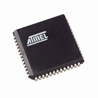
AT89C5131A-S3SUL Atmel, AT89C5131A-S3SUL Datasheet - Page 129

AT89C5131A-S3SUL
Manufacturer Part Number
AT89C5131A-S3SUL
Description
MCU 8051 32K FLASH USB 52-PLCC
Manufacturer
Atmel
Series
AT89C513xr
Specifications of AT89C5131A-S3SUL
Core Processor
C52X2
Core Size
8-Bit
Speed
48MHz
Connectivity
I²C, SPI, UART/USART, USB
Peripherals
LED, POR, PWM, WDT
Number Of I /o
34
Program Memory Size
32KB (32K x 8)
Program Memory Type
FLASH
Eeprom Size
4K x 8
Ram Size
1.25K x 8
Voltage - Supply (vcc/vdd)
3 V ~ 3.6 V
Oscillator Type
Internal
Operating Temperature
-40°C ~ 85°C
Package / Case
52-PLCC
Processor Series
AT89x
Core
8051
Data Bus Width
8 bit
Data Ram Size
1.25 KB
Interface Type
2-Wire, EUART, SPI, USB
Maximum Clock Frequency
48 MHz
Number Of Programmable I/os
34
Number Of Timers
3 bit
Operating Supply Voltage
3 V to 3.6 V
Maximum Operating Temperature
+ 85 C
Mounting Style
SMD/SMT
3rd Party Development Tools
PK51, CA51, A51, ULINK2
Development Tools By Supplier
AT89STK-05
Minimum Operating Temperature
- 40 C
For Use With
AT89STK-10 - KIT EVAL APPL MASS STORAGEAT89STK-05 - KIT STARTER FOR AT89C5131
Lead Free Status / RoHS Status
Lead free / RoHS Compliant
Data Converters
-
Lead Free Status / Rohs Status
Details
Available stocks
Company
Part Number
Manufacturer
Quantity
Price
Miscellaneous
USB Reset
STALL Handshake
Start of Frame Detection
Frame Number
Data Toggle Bit
4338F–USB–08/07
The EORINT bit in the USBINT register is set by hardware when a End Of Reset has
been detected on the USB bus. This triggers a USB interrupt if enabled. The USB con-
troller is still enabled, but all the USB registers are reset by hardware. The firmware will
clear the EORINT bit to allow the next USB reset detection.
This function is only available for Control, Bulk, and Interrupt endpoints.
The firmware has to set the STALLRQ bit in the UEPSTAX register to send a STALL
handshake at the next request of the Host on the endpoint selected with the UEPNUM
register. The RXSETUP, TXRDY, TXCMPL, RXOUTB0 and RXOUTB1 bits must be first
reset to 0. The bit STLCRC is set at 1 by the USB controller when a STALL has been
sent. This triggers an interrupt if enabled.
The firmware will clear the STALLRQ and STLCRC bits after each STALL sent.
The STALLRQ bit is cleared automatically by hardware when a valid SETUP PID is
received on a CONTROL type endpoint.
Important note: when a Clear Halt Feature occurs for an endpoint, the firmware will reset
this endpoint using the UEPRST register in order to reset the data toggle management.
The SOFINT bit in the USBINT register is set when the USB controller detects a Start of
Frame PID. This triggers an interrupt if enabled. The firmware will clear the SOFINT bit
to allow the next Start of Frame detection.
When receiving a Start of Frame, the frame number is automatically stored in the
UFNUML and UFNUMH registers. The CRCOK and CRCERR bits indicate if the CRC of
the last Start of Frame is valid (CRCOK set at 1) or corrupted (CRCERR set at 1). The
UFNUML and UFNUMH registers are automatically updated when receiving a new Start
of Frame.
The Data Toggle bit is set by hardware when a DATA0 packet is received and accepted
by the USB controller and cleared by hardware when a DATA1 packet is received and
accepted by the USB controller. This bit is reset when the firmware resets the endpoint
FIFO using the UEPRST register.
For Control endpoints, each SETUP transaction starts with a DATA0 and data toggling
is then used as for Bulk endpoints until the end of the Data stage (for a control write
transfer). The Status stage completes the data transfer with a DATA1 (for a control read
transfer).
For Isochronous endpoints, the device firmware will ignore the data-toggle.
129


