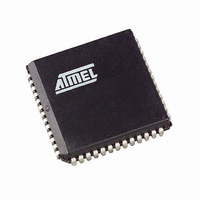
AT89C5131A-S3SUL Atmel, AT89C5131A-S3SUL Datasheet - Page 45

AT89C5131A-S3SUL
Manufacturer Part Number
AT89C5131A-S3SUL
Description
MCU 8051 32K FLASH USB 52-PLCC
Manufacturer
Atmel
Series
AT89C513xr
Specifications of AT89C5131A-S3SUL
Core Processor
C52X2
Core Size
8-Bit
Speed
48MHz
Connectivity
I²C, SPI, UART/USART, USB
Peripherals
LED, POR, PWM, WDT
Number Of I /o
34
Program Memory Size
32KB (32K x 8)
Program Memory Type
FLASH
Eeprom Size
4K x 8
Ram Size
1.25K x 8
Voltage - Supply (vcc/vdd)
3 V ~ 3.6 V
Oscillator Type
Internal
Operating Temperature
-40°C ~ 85°C
Package / Case
52-PLCC
Processor Series
AT89x
Core
8051
Data Bus Width
8 bit
Data Ram Size
1.25 KB
Interface Type
2-Wire, EUART, SPI, USB
Maximum Clock Frequency
48 MHz
Number Of Programmable I/os
34
Number Of Timers
3 bit
Operating Supply Voltage
3 V to 3.6 V
Maximum Operating Temperature
+ 85 C
Mounting Style
SMD/SMT
3rd Party Development Tools
PK51, CA51, A51, ULINK2
Development Tools By Supplier
AT89STK-05
Minimum Operating Temperature
- 40 C
For Use With
AT89STK-10 - KIT EVAL APPL MASS STORAGEAT89STK-05 - KIT STARTER FOR AT89C5131
Lead Free Status / RoHS Status
Lead free / RoHS Compliant
Data Converters
-
Lead Free Status / Rohs Status
Details
Available stocks
Company
Part Number
Manufacturer
Quantity
Price
- Current page: 45 of 186
- Download datasheet (2Mb)
Application-
Programming-Interface
XROW Bytes
Hardware Conditions
High Pin Count Hardware
Conditions (PLCC52, QFP64)
4338F–USB–08/07
Several Application Program Interface (API) calls are available for use by an application
program to permit selective erasing and programming of Flash pages. All calls are made
by functions.
All these APIs are described in detail in the following document on the Atmel web site.
The EXTRA ROW (XROW) includes 128 bytes. Some of these bytes are used for spe-
cific purpose in conjonction with the bootloader.
Table 43. XROW Mapping
It is possible to force the controller to execute the bootloader after a Reset with hard-
ware conditions. Depending on the product type (low pin count or high pin count
package), there are two methods to apply the hardware conditions.
For high pin count packages, the hardware conditons (EA = 1, PSEN = 0) are sampled
during the RESET rising edge to force the on-chip bootloader execution (See Figure 82
on page 172). In this way the bootloader can be carried out regardless of the user Flash
memory content. It is recommended to pull the PSEN pin down to ground though a 1K
resistor to prevent the PSEN pin from being damaged (See Figure 24 below).
Figure 24. ISP Hardware conditions
Description
Copy of the Manufacturer Code
Copy of the Device ID#1: Family code
Copy of the Device ID#2: Memories size and type
Copy of the Device ID#3: Name and Revision
–
GND
Datasheet Bootloader USB AT89C5131.
1K
GND
VCC
/RST
EA
/PSEN
Bootloader
VCC
VSS
GND
VCC
XTAL2
XTAL1
ALE
Unconnected
C2
Crystal
C1
GND
GND
Default Value
D7h
BBh
FFh
58h
AT89C5131A-L
Address
30h
31h
60h
61h
45
Related parts for AT89C5131A-S3SUL
Image
Part Number
Description
Manufacturer
Datasheet
Request
R

Part Number:
Description:
Manufacturer:
Atmel Corporation
Datasheet:

Part Number:
Description:
Manufacturer:
Atmel Corporation
Datasheet:

Part Number:
Description:
IC 8051 MCU FLASH 32K USB 32QFN
Manufacturer:
Atmel
Datasheet:

Part Number:
Description:
IC 8051 MCU FLASH 32K USB 52PLCC
Manufacturer:
Atmel
Datasheet:

Part Number:
Description:
IC MCU 32KB 3-3.6V USB 48-VQFN
Manufacturer:
Atmel
Datasheet:

Part Number:
Description:
MCU 8051 32K FLASH USB 28-SOIC
Manufacturer:
Atmel
Datasheet:

Part Number:
Description:
IC 8051 MCU FLASH 32K USB 64VQFP
Manufacturer:
Atmel
Datasheet:

Part Number:
Description:
MCU 8051 32K FLASH USB 64-VQFP
Manufacturer:
Atmel
Datasheet:

Part Number:
Description:
MCU 8051 32K FLASH USB 28-SOIC
Manufacturer:
Atmel
Datasheet:

Part Number:
Description:
IC 8051 MCU FLASH 32K USB 48QFN
Manufacturer:
Atmel
Datasheet:

Part Number:
Description:
IC 8051 MCU FLASH 32K USB 64VQFP
Manufacturer:
Atmel
Datasheet:

Part Number:
Description:
IC 8051 MCU FLASH 32K USB 32QFN
Manufacturer:
Atmel
Datasheet:

Part Number:
Description:
IC 8051 MCU FLASH 32K USB 52PLCC
Manufacturer:
Atmel
Datasheet:

Part Number:
Description:
IC 8051 MCU FLASH 32K USB 28SOIC
Manufacturer:
Atmel
Datasheet:


