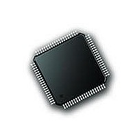
PIC18F87J72-I/PT Microchip Technology, PIC18F87J72-I/PT Datasheet - Page 210

PIC18F87J72-I/PT
Manufacturer Part Number
PIC18F87J72-I/PT
Description
IC PIC MCU 8BIT 14KB FLSH 80TQFP
Manufacturer
Microchip Technology
Series
PIC® 18Fr
Datasheet
1.PIC18F86J72-IPT.pdf
(480 pages)
Specifications of PIC18F87J72-I/PT
Program Memory Type
FLASH
Program Memory Size
128KB (64K x 16)
Package / Case
80-TQFP
Core Processor
PIC
Core Size
8-Bit
Speed
48MHz
Connectivity
I²C, LIN, SPI, UART/USART
Peripherals
Brown-out Detect/Reset, LCD, LVD, POR, PWM, WDT
Number Of I /o
51
Ram Size
3.8K x 8
Voltage - Supply (vcc/vdd)
2 V ~ 3.6 V
Data Converters
A/D 12x12b
Oscillator Type
Internal
Operating Temperature
-40°C ~ 85°C
Data Bus Width
8 bit
Data Ram Size
4 KB
Interface Type
SPI, USART, SPI, I2C
Maximum Clock Frequency
8 MHz
Number Of Programmable I/os
51
Number Of Timers
4
Operating Supply Voltage
2 V to 3.6 V
Maximum Operating Temperature
+ 85 C
Mounting Style
SMD/SMT
Minimum Operating Temperature
- 40 C
On-chip Adc
14
Controller Family/series
PIC18F
No. Of I/o's
51
Ram Memory Size
3923Byte
Cpu Speed
48MHz
No. Of Timers
4
Rohs Compliant
Yes
Lead Free Status / RoHS Status
Lead free / RoHS Compliant
Lead Free Status / RoHS Status
Lead free / RoHS Compliant, Lead free / RoHS Compliant
Available stocks
Company
Part Number
Manufacturer
Quantity
Price
Company:
Part Number:
PIC18F87J72-I/PT
Manufacturer:
Microchip
Quantity:
210
Company:
Part Number:
PIC18F87J72-I/PT
Manufacturer:
Microchip Technology
Quantity:
10 000
- Current page: 210 of 480
- Download datasheet (5Mb)
PIC18F87J72 FAMILY
18.4.3.2
Masking an address bit causes that bit to become a
“don’t care”. When one address bit is masked, two
addresses will be Acknowledged and cause an
interrupt. It is possible to mask more than one address
bit at a time, which makes it possible to Acknowledge
up to 31 addresses in 7-bit mode and up to
63 addresses in 10-bit mode (see Example 18-2).
The I
masking is used or not. However, when address
masking is used, the I
multiple addresses and cause interrupts. When this
occurs, it is necessary to determine which address
caused the interrupt by checking SSPBUF.
In 7-Bit Addressing mode, Address Mask bits,
ADMSK<5:1> (SSPCON<5:1>), mask the correspond-
ing address bits in the SSPADD register. For any ADMSK
bits that are set (ADMSK<x> = 1), the corresponding
address bit is ignored (SSPADD<x> = x). For the module
to issue an address Acknowledge, it is sufficient to match
only on addresses that do not have an active address
mask.
EXAMPLE 18-2:
DS39979A-page 210
7-Bit Addressing:
10-Bit Addressing:
2
C Slave behaves the same way whether address
SSPADD<7:1> = A0h (1010000) (SSPADD<0> is assumed to be ‘0’)
ADMSK<5:1>
Addresses Acknowledged: A0h, A2h, A4h, A6h, A8h, AAh, ACh, AEh
SSPADD<7:0> = A0h (10100000) (the two MSbs of the address are ignored in this example, since they are
not affected by masking)
ADMSK<5:1>
Addresses Acknowledged: A0h, A1h, A2h, A3h, A4h, A5h, A6h, A7h, A8h, A9h, AAh, ABh, ACh, ADh, AEh, AFh
Address Masking
ADDRESS MASKING EXAMPLES
= 00111
= 00111
2
C slave can Acknowledge
Preliminary
In 10-Bit Addressing mode, ADMSK<5:2> bits mask
the corresponding address bits in the SSPADD regis-
ter. In addition, ADMSK1 simultaneously masks the two
LSbs of the address (SSPADD<1:0>). For any ADMSK
bits that are active (ADMSK<x> = 1), the correspond-
ing address bit is ignored (SSPADD<x> = x). Also note,
that although in 10-Bit Addressing mode, the upper
address bits reuse part of the SSPADD register bits; the
address mask bits do not interact with those bits. They
only affect the lower address bits.
Note 1: ADMSK1 masks the two Least Significant
2: The two Most Significant bits of the
bits of the address.
address are not affected by address
masking.
2010 Microchip Technology Inc.
Related parts for PIC18F87J72-I/PT
Image
Part Number
Description
Manufacturer
Datasheet
Request
R

Part Number:
Description:
Manufacturer:
Microchip Technology Inc.
Datasheet:

Part Number:
Description:
Manufacturer:
Microchip Technology Inc.
Datasheet:

Part Number:
Description:
Manufacturer:
Microchip Technology Inc.
Datasheet:

Part Number:
Description:
Manufacturer:
Microchip Technology Inc.
Datasheet:

Part Number:
Description:
Manufacturer:
Microchip Technology Inc.
Datasheet:

Part Number:
Description:
Manufacturer:
Microchip Technology Inc.
Datasheet:

Part Number:
Description:
Manufacturer:
Microchip Technology Inc.
Datasheet:

Part Number:
Description:
Manufacturer:
Microchip Technology Inc.
Datasheet:


