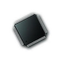
PIC18F87J72-I/PT Microchip Technology, PIC18F87J72-I/PT Datasheet - Page 292

PIC18F87J72-I/PT
Manufacturer Part Number
PIC18F87J72-I/PT
Description
IC PIC MCU 8BIT 14KB FLSH 80TQFP
Manufacturer
Microchip Technology
Series
PIC® 18Fr
Datasheet
1.PIC18F86J72-IPT.pdf
(480 pages)
Specifications of PIC18F87J72-I/PT
Program Memory Type
FLASH
Program Memory Size
128KB (64K x 16)
Package / Case
80-TQFP
Core Processor
PIC
Core Size
8-Bit
Speed
48MHz
Connectivity
I²C, LIN, SPI, UART/USART
Peripherals
Brown-out Detect/Reset, LCD, LVD, POR, PWM, WDT
Number Of I /o
51
Ram Size
3.8K x 8
Voltage - Supply (vcc/vdd)
2 V ~ 3.6 V
Data Converters
A/D 12x12b
Oscillator Type
Internal
Operating Temperature
-40°C ~ 85°C
Data Bus Width
8 bit
Data Ram Size
4 KB
Interface Type
SPI, USART, SPI, I2C
Maximum Clock Frequency
8 MHz
Number Of Programmable I/os
51
Number Of Timers
4
Operating Supply Voltage
2 V to 3.6 V
Maximum Operating Temperature
+ 85 C
Mounting Style
SMD/SMT
Minimum Operating Temperature
- 40 C
On-chip Adc
14
Controller Family/series
PIC18F
No. Of I/o's
51
Ram Memory Size
3923Byte
Cpu Speed
48MHz
No. Of Timers
4
Rohs Compliant
Yes
Lead Free Status / RoHS Status
Lead free / RoHS Compliant
Lead Free Status / RoHS Status
Lead free / RoHS Compliant, Lead free / RoHS Compliant
Available stocks
Company
Part Number
Manufacturer
Quantity
Price
Company:
Part Number:
PIC18F87J72-I/PT
Manufacturer:
Microchip
Quantity:
210
Company:
Part Number:
PIC18F87J72-I/PT
Manufacturer:
Microchip Technology
Quantity:
10 000
- Current page: 292 of 480
- Download datasheet (5Mb)
PIC18F87J72 FAMILY
EXAMPLE 22-5:
DS39979A-page 292
/////////////////////////////////////////////////////////////////////////////////////////////
// STEP 7: Reading AFE results in Interrupt Routine.
// ADC is configured in 16-bit result mode, thus 16-bit result of each Channel can be read.
// In this example DR is connected to INT0; after each convesion, DR issues interrupt to INT0.
// INT0 is configured as high priority interrupt
////////////////////////////////////////////////////////////////////////////////////////////
#pragma interrupt High_isr_routine
void High_isr_routine(void)
{
char
}
#pragma code High_isr=0x08
void High_ISR(void)
{
}
_asm goto High_isr_routine _endasm
if((INTCONbits.INT0IF)&&(INTCONbits.INT0IE))
{
}
D_S_ADC_data1=0,D_S_ADC_data2=0,D_S_ADC_data3=0,D_S_ADC_data4=0,Dummy_Read=0;
//
LATDbits.LATD7=0;
SSP1BUF = 0x01;
while(!SSPSTATbits.BF);
Dummy_Read=SSPBUF;
SSPBUF =0x00;
while(!SSPSTATbits.BF);
D_S_ADC_data1=SSPBUF;
SSPBUF = 0x00;
while(!SSPSTATbits.BF);
D_S_ADC_data2=SSPBUF;
SSPBUF = 0x00;
while(!SSPSTATbits.BF);
D_S_ADC_data3=SSPBUF;
SSPBUF = 0x00;
while(!SSPSTATbits.BF);
D_S_ADC_data4=SSPBUF;
LATDbits.LATD7=1;
INTCONbits.INT0IF=0;
Disable all Chip selects of other devices connected to SPI
READING DATA FROM AFE DURING INTERRUPT
//Chip select enable for Delta Sigma ADC
//Address and Read command for Channel0 result MSB register
//Dummy read to clear Buffer Full Status bit
//Data from Channel0 MSB
//Data from Channel0 LSB, Address automatically incremented
//Data from Channel1 MSB, Address automatically incremented
//Data from Channel1 LSB, Address automatically incremented
//Disable chip select after read/write of registers
//Clear INT0IF for next interrupt
Preliminary
2010 Microchip Technology Inc.
Related parts for PIC18F87J72-I/PT
Image
Part Number
Description
Manufacturer
Datasheet
Request
R

Part Number:
Description:
Manufacturer:
Microchip Technology Inc.
Datasheet:

Part Number:
Description:
Manufacturer:
Microchip Technology Inc.
Datasheet:

Part Number:
Description:
Manufacturer:
Microchip Technology Inc.
Datasheet:

Part Number:
Description:
Manufacturer:
Microchip Technology Inc.
Datasheet:

Part Number:
Description:
Manufacturer:
Microchip Technology Inc.
Datasheet:

Part Number:
Description:
Manufacturer:
Microchip Technology Inc.
Datasheet:

Part Number:
Description:
Manufacturer:
Microchip Technology Inc.
Datasheet:

Part Number:
Description:
Manufacturer:
Microchip Technology Inc.
Datasheet:


