CDB42L55 Cirrus Logic Inc, CDB42L55 Datasheet - Page 24
CDB42L55
Manufacturer Part Number
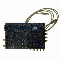
CDB42L55
Description
Eval Bd Ultra Low Power Stereo Codec
Manufacturer
Cirrus Logic Inc
Specifications of CDB42L55
Main Purpose
Audio, CODEC
Embedded
Yes, FPGA / CPLD
Utilized Ic / Part
CS42L55
Primary Attributes
2 Stereo Analog Inputs, Stereo Line and Headphone Outputs, S/PDIF Transmitter and Receiver
Secondary Attributes
GUI, USB, RS232, I2C Interfaces, USB or External or Battery Power Supply
Product
Audio Modules
Lead Free Status / RoHS Status
Contains lead / RoHS non-compliant
Lead Free Status / RoHS Status
Contains lead / RoHS non-compliant
Other names
598-1506
CDB-42L55
CDB-42L55


24
4.2.1
4.2.2
Pseudo-Differential Inputs
The CS42L55 implements a pseudo-differential input stage. The AINxREF inputs are intended to be used
as a pseudo-differential reference signal. This feature provides 0 noise rejection with single-ended sig-
nals.
put stage, including a recommended stereo pseudo-differential input topology. If pseudo-differential input
functionality is not required, simply leave the AINxREF pin floating.
Automatic Level Control (ALC)
When enabled, the ALC monitors the analog input signal after the digital attenuator. The ALC then detects
when peak levels exceed the maximum threshold settings and first lowers the PGA gain settings and then
increases the digital attenuation levels at a programmable attack rate and maintains the resulting level
below the maximum threshold.
When input signal levels fall below the minimum threshold, digital attenuation levels are decreased first
and the PGA gain is then increased at a programmable release rate and maintains the resulting level
above the minimum threshold.
Attack and release rates are affected by the ADC soft ramp/zero cross settings and sample rate, Fs. ALC
soft ramp and zero cross dependency may be independently enabled/disabled.
Recommended settings: Best level control may be realized with the fastest attack and slowest release
setting with soft ramp enabled in the control registers.
Notes:
1. When ALC x is enabled and the PGAxVOL[5:0] is set to +12 dB, the ADCxATT[7:0] should not be set
2. The maximum desired gain must be set in the PGAxVOL register. The ALC will only apply the gain
3. The ALC maintains the output signal between the MIN and MAX thresholds. As the input signal level
Right Input
Referenced Control
PGAxMUX ...........................
Left Input
below 0 dB.
set in PGAxVOL.
changes, the level-controlled output may not always be the same but will always fall between the
thresholds.
GND
GND
Figure 10
(differential traces)
(differential traces)
//
//
//
//
shows a basic diagram outlining the internal implementation of the pseudo-differential in-
Register Location
“PGA x Input Select” on page 49
Figure 10. Stereo Pseudo-Differential Input
1 µF
1 µF
1 µF
1 µF
AIN1REF
AIN2REF
AIN1A
AIN2B
26
27
25
24
+
+
-
-
common mode rejection at input of PGA reduces
PGA A
PGA B
PGAAMUX=’0'b
PGABMUX=’1'b
external system noise
CS42L55
DS773F1
Related parts for CDB42L55
Image
Part Number
Description
Manufacturer
Datasheet
Request
R

Part Number:
Description:
Development Kit
Manufacturer:
Cirrus Logic Inc
Datasheet:
Part Number:
Description:
Development Kit
Manufacturer:
Cirrus Logic Inc
Datasheet:


Part Number:
Description:
High-efficiency PFC + Fluorescent Lamp Driver Reference Design
Manufacturer:
Cirrus Logic Inc
Datasheet:
Part Number:
Description:
Development Kit
Manufacturer:
Cirrus Logic Inc
Datasheet:
Part Number:
Description:
Development Kit
Manufacturer:
Cirrus Logic Inc
Datasheet:

Part Number:
Description:
Development Kit
Manufacturer:
Cirrus Logic Inc
Datasheet:
Part Number:
Description:
Development Kit
Manufacturer:
Cirrus Logic Inc
Datasheet:
Part Number:
Description:
Development Kit
Manufacturer:
Cirrus Logic Inc
Datasheet:
Part Number:
Description:
Development Kit
Manufacturer:
Cirrus Logic Inc
Datasheet:

Part Number:
Description:
EVALUATION BOARD FOR CS8427
Manufacturer:
Cirrus Logic Inc
Datasheet:

Part Number:
Description:
BOARD EVAL FOR CS8416 RCVR
Manufacturer:
Cirrus Logic Inc
Datasheet:

Part Number:
Description:
EVALUATION BOARD FOR CS8420
Manufacturer:
Cirrus Logic Inc
Datasheet:

Part Number:
Description:
KIT DEVELOPMENT EP9315 ARM9
Manufacturer:
Cirrus Logic Inc
Datasheet:

Part Number:
Description:
KIT DEVELOPMENT EP9302 ARM9
Manufacturer:
Cirrus Logic Inc
Datasheet: