CDB42L55 Cirrus Logic Inc, CDB42L55 Datasheet - Page 71
CDB42L55
Manufacturer Part Number
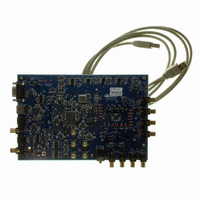
CDB42L55
Description
Eval Bd Ultra Low Power Stereo Codec
Manufacturer
Cirrus Logic Inc
Specifications of CDB42L55
Main Purpose
Audio, CODEC
Embedded
Yes, FPGA / CPLD
Utilized Ic / Part
CS42L55
Primary Attributes
2 Stereo Analog Inputs, Stereo Line and Headphone Outputs, S/PDIF Transmitter and Receiver
Secondary Attributes
GUI, USB, RS232, I2C Interfaces, USB or External or Battery Power Supply
Product
Audio Modules
Lead Free Status / RoHS Status
Contains lead / RoHS non-compliant
Lead Free Status / RoHS Status
Contains lead / RoHS non-compliant
Other names
598-1506
CDB-42L55
CDB-42L55


DS773F1
10.PARAMETER DEFINITIONS
Dynamic Range
Total Harmonic Distortion + Noise
Frequency Response
Interchannel Isolation
HP to ADC Isolation
Output Offset Voltage
AC Load Resistance and Capacitance
Interchannel Gain Mismatch
Gain Error
Gain Drift
Offset Error
The ratio of the rms value of the signal to the rms sum of all other spectral components over the specified
bandwidth. Dynamic Range is a signal-to-noise ratio measurement over the specified band width made with
a -60 dB signal. 60 dB is added to resulting measurement to refer the measurement to full-scale. This tech-
nique ensures that the distortion components are below the noise level and do not affect the measurement.
This measurement technique has been accepted by the Audio Engineering Society, AES17-1991, and the
Electronic Industries Association of Japan, EIAJ CP-307. Expressed in decibels.
The ratio of the rms value of the signal to the rms sum of all other spectral components over the specified
bandwidth (typically 10 Hz to 20 kHz), including distortion components. Expressed in decibels. Measured
at -1 dBFS and -20 dBFS for the analog input and 0 dB and -20 dB for the analog output as suggested in
AES17-1991 Annex A.
A measure of the amplitude response variation from 10 Hz to 20 kHz relative to the amplitude response at
1 kHz. Units in decibels.
A measure of crosstalk between the left and right channel pairs. Measured for each channel at the convert-
er's output with no signal to the input under test and a full-scale signal applied to the other channel. Units in
decibels.
A measure of crosstalk between the headphone amplifier and the ADC inputs. Measured for each channel
at the ADC’s output with no signal to the input and a full-scale signal applied to the headphone amplifier with
a 16 Ω or 10 kΩ load. Units in decibels.
Describes the DC offset voltage present at the amplifier’s output during a MUTE state. When measuring the
offset out the line amplifier, the line amplifier is ON while the headphone amplifier is OFF; when measuring
the offset out the headphone amplifier, the headphone amplifier is ON while the line amplifier is OFF. The
offset observed at the output of the HP/Line amplifiers is a result of the non-infinite CMRR of the output am-
plifier that exists due to CMOS process limitations and is proportional to the analog volume settings.
R
nal op-amp's stability and signal integrity. C
output stage. Increasing this value beyond the recommended 150 pF can cause the internal op-amp to be-
come unstable.
The gain difference between left and right channel pairs. Units in decibels.
The deviation from the nominal full-scale analog output for a full-scale digital input.
The change in gain value with temperature. Units in ppm/°C.
The deviation of the mid-scale transition (111...111 to 000...000) from the ideal.
L
and C
L
reflect the recommended minimum resistance and maximum capacitance required for the inter-
L
will effectively move the band-limiting pole of the amp in the
CS42L55
71
Related parts for CDB42L55
Image
Part Number
Description
Manufacturer
Datasheet
Request
R

Part Number:
Description:
Development Kit
Manufacturer:
Cirrus Logic Inc
Datasheet:
Part Number:
Description:
Development Kit
Manufacturer:
Cirrus Logic Inc
Datasheet:


Part Number:
Description:
High-efficiency PFC + Fluorescent Lamp Driver Reference Design
Manufacturer:
Cirrus Logic Inc
Datasheet:
Part Number:
Description:
Development Kit
Manufacturer:
Cirrus Logic Inc
Datasheet:
Part Number:
Description:
Development Kit
Manufacturer:
Cirrus Logic Inc
Datasheet:

Part Number:
Description:
Development Kit
Manufacturer:
Cirrus Logic Inc
Datasheet:
Part Number:
Description:
Development Kit
Manufacturer:
Cirrus Logic Inc
Datasheet:
Part Number:
Description:
Development Kit
Manufacturer:
Cirrus Logic Inc
Datasheet:
Part Number:
Description:
Development Kit
Manufacturer:
Cirrus Logic Inc
Datasheet:

Part Number:
Description:
EVALUATION BOARD FOR CS8427
Manufacturer:
Cirrus Logic Inc
Datasheet:

Part Number:
Description:
BOARD EVAL FOR CS8416 RCVR
Manufacturer:
Cirrus Logic Inc
Datasheet:

Part Number:
Description:
EVALUATION BOARD FOR CS8420
Manufacturer:
Cirrus Logic Inc
Datasheet:

Part Number:
Description:
KIT DEVELOPMENT EP9315 ARM9
Manufacturer:
Cirrus Logic Inc
Datasheet:

Part Number:
Description:
KIT DEVELOPMENT EP9302 ARM9
Manufacturer:
Cirrus Logic Inc
Datasheet: