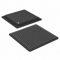
ADSP-TS101SAB2-000 Analog Devices Inc, ADSP-TS101SAB2-000 Datasheet - Page 36

ADSP-TS101SAB2-000
Manufacturer Part Number
ADSP-TS101SAB2-000
Description
IC,DSP,32-BIT,BGA,484PIN,PLASTIC
Manufacturer
Analog Devices Inc
Series
TigerSHARC®r
Type
Fixed/Floating Pointr
Datasheet
1.ADSP-TS101SAB1-000.pdf
(48 pages)
Specifications of ADSP-TS101SAB2-000
Rohs Status
RoHS non-compliant
Interface
Host Interface, Link Port, Multi-Processor
Clock Rate
250MHz
Non-volatile Memory
External
On-chip Ram
768kB
Voltage - I/o
3.30V
Voltage - Core
1.20V
Operating Temperature
-40°C ~ 85°C
Mounting Type
Surface Mount
Package / Case
484-BGA
Package
484BGA
Numeric And Arithmetic Format
Fixed-Point|Floating-Point
Maximum Speed
250 MHz
Ram Size
768 KB
Device Million Instructions Per Second
250 MIPS
Lead Free Status / RoHS Status
Other names
ADSP-TS101SAB2000
Available stocks
Company
Part Number
Manufacturer
Quantity
Price
Company:
Part Number:
ADSP-TS101SAB2-000
Manufacturer:
MINI
Quantity:
1 400
Company:
Part Number:
ADSP-TS101SAB2-000
Manufacturer:
Analog Devices Inc
Quantity:
10 000
ADSP-TS101S
1
ENVIRONMENTAL CONDITIONS
The ADSP-TS101S is rated for performance over the extended
commercial temperature range, T
Thermal Characteristics
The ADSP-TS101S is packaged in a 19 mm 19 mm and
27 mm 27 mm Plastic Ball Grid Array (PBGA). The
ADSP-TS101S is specified for a case temperature (T
The line equations for the output valid vs. load capacitance are:
Figure 40. Typical Output Valid (V
Strength 0: y = 0.0956x + 3.5662
Strength 1: y = 0.0523x + 3.2144
Strength 2: y = 0.0433x + 3.1319
Strength 3: y = 0.0391x + 2.9675
Strength 4: y = 0.0393x + 2.7653
Strength 5: y = 0.0373x + 2.6515
Strength 6: y = 0.0379x + 2.1206
Strength 7: y = 0.0399x + 1.9080
Figure 39. Typical Output Rise and Fall Time (10%–90%, V
15
10
25
20
15
10
5
0
5
0
0
0
y = 0.0907x + 1.0071
10
10
RISE TIME
Case Temperature and Strength 0–7
20
20
vs. Load Capacitance at Strength 7
30
30
LOAD CAPACITANCE (pF)
LOAD CAPACITANCE (pF)
STRENGTH 0-7
(V
(V
40
40
STRENGTH 7
DD_IO
DD_IO
DD_IO
50
50
= 3.3V)
= 3.3V)
= 3.3 V) vs. Load Capacitance at Max
CASE
60
60
= –40°C to +85°C.
70
70
y = 0.09x + 0.3134
80
80
FALL TIME
1
90
90
CASE
DD_IO
Rev. C | Page 36 of 48 | May 2009
100
100
). To
= 3.3 V)
0
1
2
3
4
5
6
7
ensure that the T
heat sink and/or an air flow source may be used. See
and
Table 33. Thermal Characteristics
for 19 mm 19 mm Package
1
2
3
Table 34. Thermal Characteristics
for 27 mm 27 mm Package
1
2
3
Parameter
Parameter
Determination of parameter is system dependent and is based on a number of
Per JEDEC JESD51-2 procedure using a four layer board (compliant with JEDEC
Per SEMI Test Method G38-87 using a four layer board (compliant with JEDEC
Determination of parameter is system dependent and is based on a number of
Per JEDEC JESD51-2 procedure using a four layer board (compliant with JEDEC
Per SEMI Test Method G38-87 using a four layer board (compliant with JEDEC
factors, including device power dissipation, package thermal resistance, board
thermal characteristics, ambient temperature, and air flow.
JESD51-9).
JESD51-9).
factors, including device power dissipation, package thermal resistance, board
thermal characteristics, ambient temperature, and air flow.
JESD51-9).
JESD51-9).
JA
JC
JB
JA
JC
JB
1
1
Table 34
for thermal data.
CASE
Condition
Airflow
Airflow
Airflow
Condition
Airflow
Airflow
Airflow
data sheet specification is not exceeded, a
2
3
3
2
3
3
= 0 m/s
= 1 m/s
= 2 m/s
= 0 m/s
= 1 m/s
= 2 m/s
Typical
16.6
14.0
12.9
6.7
5.8
Typical
13.8
11.7
10.8
3.1
5.9
Table 33
Unit
°C/W
°C/W
°C/W
°C/W
°C/W
Unit
°C/W
°C/W
°C/W
°C/W
°C/W


