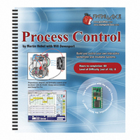
122-28176 Parallax Inc, 122-28176 Datasheet - Page 265

122-28176
Manufacturer Part Number
122-28176
Description
GUIDE STUDENT PROCESS CONTROL
Manufacturer
Parallax Inc
Specifications of 122-28176
Accessory Type
Manual
Product
Microcontroller Accessories
Lead Free Status / RoHS Status
Contains lead / RoHS non-compliant
For Use With/related Products
Propeller Education (PE) Kit
Lead Free Status / RoHS Status
Lead free / RoHS Compliant, Contains lead / RoHS non-compliant
- Current page: 265 of 330
- Download datasheet (11Mb)
Derivate drive is based on the rate of change of the error – how quickly the error changed
between samples:
Using discrete PID measurements, the PID formula becomes
Since we are on the subject of using light levels for PID control as used in the Floating
Ball project, let's experiement with PID evaluation using light. In the next activity, we'll
build a light-sensing system and use it to experiment with the effect of proportional (P),
integral (I) and derivative (D) control, both singularly and in combination. The system
consists of a photoresistor to sense the amount of light, and your hand, to either cast
shade or allow more light onto the sensor. Your hand, then, creates disturbances to the
system, and the photoresistor senses the system variable, in this case, light intensity. This
system will demonstrate the PID evaluations of a system, but it is not actually
representative of the response of a closed-loop system, as there is no electro-mechanical
system in place to control the light level based on the PID evaluations.
Consider, though, if the light level was influenced by the amount of light coming in
through a window, and we had a motor connected to windows blinds. As the light level
increased during the day, the motor would close the blinds in an attempt to maintain light
level at the setpoint. In such a system, the output drive values would directly control the
motor. For a Parallax Standard Servo motor and the BS2, reasonable drive values would
range 500 to 1000. However, for this activity, we are going to simply output values that
are in the same range as those of the light sensor, about 0 to 2000 or so. Our output
values will not be values that are needed for actual control.
DERIVATIVE = (E
Co
PID
= Bias + K
P
E + K
4
-E
3
I
) / (t
ΣE∆t + K
4
−t
3
) = ∆E/∆t
D
∆E/∆t
Figure 8-6
Discrete PID
measurements
Related parts for 122-28176
Image
Part Number
Description
Manufacturer
Datasheet
Request
R

Part Number:
Description:
MANUAL FOR SUMOBOT
Manufacturer:
Parallax Inc
Datasheet:

Part Number:
Description:
GUIDE STUDENT SMART SENSORS
Manufacturer:
Parallax Inc
Datasheet:

Part Number:
Description:
MANUAL PROPELLER
Manufacturer:
Parallax Inc
Datasheet:

Part Number:
Description:
LEAD WIRES FLYING CABLE III/IV
Manufacturer:
Xilinx Inc
Datasheet:

Part Number:
Description:
BOARD ADAPTER AND FLY LEADS
Manufacturer:
Xilinx Inc
Datasheet:

Part Number:
Description:
PLATFORM CABLE USB II
Manufacturer:
Xilinx Inc
Datasheet:

Part Number:
Description:
KIT STARTER COOLRUNNER-II BUNDLE
Manufacturer:
Xilinx Inc
Datasheet:

Part Number:
Description:
Microcontroller Modules & Accessories DISCONTINUED BY PARALLAX
Manufacturer:
Parallax Inc

Part Number:
Description:
Microcontroller Modules & Accessories DISCONTINUED BY PARALLAX
Manufacturer:
Parallax Inc

Part Number:
Description:
BOOK UNDERSTANDING SIGNALS
Manufacturer:
Parallax Inc
Datasheet:

Part Number:
Description:
BOARD EXPERIMENT+LCD NX-1000
Manufacturer:
Parallax Inc
Datasheet:

Part Number:
Description:
IC MCU 2K FLASH 50MHZ SO-18
Manufacturer:
Parallax Inc
Datasheet:


