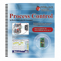
122-28176 Parallax Inc, 122-28176 Datasheet - Page 55

122-28176
Manufacturer Part Number
122-28176
Description
GUIDE STUDENT PROCESS CONTROL
Manufacturer
Parallax Inc
Specifications of 122-28176
Accessory Type
Manual
Product
Microcontroller Accessories
Lead Free Status / RoHS Status
Contains lead / RoHS non-compliant
For Use With/related Products
Propeller Education (PE) Kit
Lead Free Status / RoHS Status
Lead free / RoHS Compliant, Contains lead / RoHS non-compliant
- Current page: 55 of 330
- Download datasheet (11Mb)
Chapter 3: Digital Input Conditioning · Page 45
Chapter 3: Digital Input Conditioning
Digital Input seems pretty cut and dried. An input voltage at Vdd is recognized as a
digital HIGH (binary 1). An input voltage at Vss (ground) is recognized as a digital
LOW (binary 0). However, what if the BASIC Stamp input is not connected to either?
What state will it assume, if any? What if the input is 2.5 V?
Devices which supply an input to the BASIC Stamp may not always provide +5 V for a
HIGH and 0 V for a LOW. It is important to understand the digital input characteristics
of the BASIC Stamp. Also important are the proper techniques of conditioning signals
from mechanical input devices such as pushbuttons. Conditioning from electronic input
devices is also frequently necessary as well.
In this chapter we will explore the input characteristics of the BASIC Stamp, the basic
operation of a BJT (Bipolar Junction Transistor) and mechanical and electronic switch
interfacing.
ACTIVITY #1: MEASURING THE THRESHOLD VOLTAGE
A HIGH level, or logic 1, is typically the positive voltage of the system. A LOW level,
or logic 0, is typically the negative supply, or ground reference, of the system. For the
BASIC Stamp these are labeled Vdd (+5 V) and Vss (0 V, which is “ground”).
What if the voltage at the input were 3.5 V? Is this HIGH or LOW? What about 2.5 V?
2.0 V? 1.0 V? Since a digital system only can be one of two states, at what input voltage
do the HIGH and LOW states transition? This activity will measure the threshold voltage
below which the input is LOW and above which the input is HIGH. An Analog to
Digital Converter (ADC) will be used to measure and plot the voltage levels at the input.
A full discussion of the ADC is covered in Chapter 6.
Parts Required
(1) ADC0831 Analog to Digital Converter
(1) 10 kΩ Single-Turn Potentiometer
(2) 220 Ω Resistor
(1) LED – Red
Related parts for 122-28176
Image
Part Number
Description
Manufacturer
Datasheet
Request
R

Part Number:
Description:
MANUAL FOR SUMOBOT
Manufacturer:
Parallax Inc
Datasheet:

Part Number:
Description:
GUIDE STUDENT SMART SENSORS
Manufacturer:
Parallax Inc
Datasheet:

Part Number:
Description:
MANUAL PROPELLER
Manufacturer:
Parallax Inc
Datasheet:

Part Number:
Description:
LEAD WIRES FLYING CABLE III/IV
Manufacturer:
Xilinx Inc
Datasheet:

Part Number:
Description:
BOARD ADAPTER AND FLY LEADS
Manufacturer:
Xilinx Inc
Datasheet:

Part Number:
Description:
PLATFORM CABLE USB II
Manufacturer:
Xilinx Inc
Datasheet:

Part Number:
Description:
KIT STARTER COOLRUNNER-II BUNDLE
Manufacturer:
Xilinx Inc
Datasheet:

Part Number:
Description:
Microcontroller Modules & Accessories DISCONTINUED BY PARALLAX
Manufacturer:
Parallax Inc

Part Number:
Description:
Microcontroller Modules & Accessories DISCONTINUED BY PARALLAX
Manufacturer:
Parallax Inc

Part Number:
Description:
BOOK UNDERSTANDING SIGNALS
Manufacturer:
Parallax Inc
Datasheet:

Part Number:
Description:
BOARD EXPERIMENT+LCD NX-1000
Manufacturer:
Parallax Inc
Datasheet:

Part Number:
Description:
IC MCU 2K FLASH 50MHZ SO-18
Manufacturer:
Parallax Inc
Datasheet:


