C8051F410DK Silicon Laboratories Inc, C8051F410DK Datasheet - Page 182
C8051F410DK
Manufacturer Part Number
C8051F410DK
Description
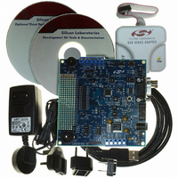
KIT DEV FOR C8051F41X
Manufacturer
Silicon Laboratories Inc
Type
MCUr
Specifications of C8051F410DK
Contents
Evaluation Board, Power Supply, USB Cables, Adapter and Documentation
Processor To Be Evaluated
C8051F41x
Interface Type
USB
Silicon Manufacturer
Silicon Labs
Core Architecture
8051
Silicon Core Number
C8051F410
Silicon Family Name
C8051F41x
Lead Free Status / RoHS Status
Contains lead / RoHS non-compliant
For Use With/related Products
Silicon Laboratories C8051F41x
Lead Free Status / Rohs Status
Lead free / RoHS Compliant
Other names
336-1314
Available stocks
Company
Part Number
Manufacturer
Quantity
Price
Company:

Part Number:
C8051F410DK
Manufacturer:
Silicon Labs
Quantity:
135


C8051F410/1/2/3
20.2. smaRTClock Clocking Sources
The smaRTClock peripheral is clocked from its own timebase, independent of SYSCLK. The RTCCLK
timebase is derived from the smaRTClock oscillator circuit. This oscillator has two modes of operation:
Crystal Mode, and Self-Oscillate Mode. The oscillation frequency is 32.768 kHz in Crystal Mode and can
be configured to roughly 20 kHz or 40 kHz in Self-Oscillate Mode. The frequency of the smaRTClock oscil-
lator can be measured with respect to another oscillator using Timer 2 or Timer 3. Section
“
Note: The smaRTClock clock can be selected as system clock and routed to a port pin. See SFR
Definition 19.5. “CLKSEL: Clock Select” on page 174 and Section “
20.2.1. Using the smaRTClock Oscillator in Crystal Mode
When using Crystal Mode, a 32.768 kHz crystal should be connected between XTAL3 and XTAL4. No
other external components are required. The following steps show how to start the smaRTClock crystal
oscillator in software:
20.2.2. Using the smaRTClock Oscillator in Self-Oscillate Mode
When using Self-Oscillate Mode, the XTAL3 and XTAL4 pins should be shorted together. The following
steps show how to configure smaRTClock for use in Self-Oscillate Mode:
182
24.2.3. External/smaRTClock Capture Mode
Note: Software should avoid read modify write instructions when writing values to RTC0DAT.
Bits 7–0: RTC0DAT. smaRTClock Data Bits
R/W
Bit7
Step 1. Set smaRTClock to Crystal Mode (XMODE = 1).
Step 2. Optional. Enable Automatic Gain Control (AGCEN = 1).
Step 3. Optional. Enable smaRTClock Bias Doubling (BIASX2 = 1).
Step 4. Enable power to the smaRTClock oscillator circuit (RTC0EN = 1).
Step 5. Poll the smaRTClock Clock Valid Bit (CLKVLD) until the crystal oscillator stabilizes.
Step 6. Optional . Clear BIASX2 to ‘0’ after the oscillator stabilizes to conserve power.
Step 1. Set smaRTClock to Self-Oscillate Mode (XMODE = 0).
Step 2. Set the desired oscillation frequency:
Step 3. The oscillator starts oscillating instantaneously.
Holds data transferred to/from the internal smaRTClock register selected by RTC0ADR.
For oscillation at about 20 kHz, set BIASX2 = 0.
For oscillation at about 40 kHz, set BIASX2 = 1.
R/W
Bit6
SFR Definition 20.3. RTC0DAT: smaRTClock Data
R/W
Bit5
R/W
Bit4
” on page
Rev. 1.1
R/W
Bit3
241
shows how this can be accomplished.
R/W
Bit2
18. Port Input/Output
R/W
Bit1
SFR Address:
R/W
Bit0
” on page
0xAD
Reset Value
Variable
147
.
Related parts for C8051F410DK
Image
Part Number
Description
Manufacturer
Datasheet
Request
R

Part Number:
Description:
SMD/C°/SINGLE-ENDED OUTPUT SILICON OSCILLATOR
Manufacturer:
Silicon Laboratories Inc
Part Number:
Description:
Manufacturer:
Silicon Laboratories Inc
Datasheet:
Part Number:
Description:
N/A N/A/SI4010 AES KEYFOB DEMO WITH LCD RX
Manufacturer:
Silicon Laboratories Inc
Datasheet:
Part Number:
Description:
N/A N/A/SI4010 SIMPLIFIED KEY FOB DEMO WITH LED RX
Manufacturer:
Silicon Laboratories Inc
Datasheet:
Part Number:
Description:
N/A/-40 TO 85 OC/EZLINK MODULE; F930/4432 HIGH BAND (REV E/B1)
Manufacturer:
Silicon Laboratories Inc
Part Number:
Description:
EZLink Module; F930/4432 Low Band (rev e/B1)
Manufacturer:
Silicon Laboratories Inc
Part Number:
Description:
I°/4460 10 DBM RADIO TEST CARD 434 MHZ
Manufacturer:
Silicon Laboratories Inc
Part Number:
Description:
I°/4461 14 DBM RADIO TEST CARD 868 MHZ
Manufacturer:
Silicon Laboratories Inc
Part Number:
Description:
I°/4463 20 DBM RFSWITCH RADIO TEST CARD 460 MHZ
Manufacturer:
Silicon Laboratories Inc
Part Number:
Description:
I°/4463 20 DBM RADIO TEST CARD 868 MHZ
Manufacturer:
Silicon Laboratories Inc
Part Number:
Description:
I°/4463 27 DBM RADIO TEST CARD 868 MHZ
Manufacturer:
Silicon Laboratories Inc
Part Number:
Description:
I°/4463 SKYWORKS 30 DBM RADIO TEST CARD 915 MHZ
Manufacturer:
Silicon Laboratories Inc
Part Number:
Description:
N/A N/A/-40 TO 85 OC/4463 RFMD 30 DBM RADIO TEST CARD 915 MHZ
Manufacturer:
Silicon Laboratories Inc
Part Number:
Description:
I°/4463 20 DBM RADIO TEST CARD 169 MHZ
Manufacturer:
Silicon Laboratories Inc