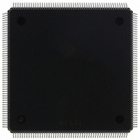
MCF5407AI220 Freescale Semiconductor, MCF5407AI220 Datasheet - Page 197

MCF5407AI220
Manufacturer Part Number
MCF5407AI220
Description
IC MPU 32B 220MHZ COLDF 208-FQFP
Manufacturer
Freescale Semiconductor
Series
MCF540xr
Specifications of MCF5407AI220
Core Processor
Coldfire V4
Core Size
32-Bit
Speed
220MHz
Connectivity
EBI/EMI, I²C, UART/USART
Peripherals
DMA, WDT
Number Of I /o
16
Program Memory Type
ROMless
Ram Size
4K x 8
Voltage - Supply (vcc/vdd)
1.65 V ~ 3.6 V
Oscillator Type
External
Operating Temperature
0°C ~ 70°C
Package / Case
208-FQFP
Maximum Clock Frequency
220 MHz
Operating Supply Voltage
1.8 V, 3.3 V
Maximum Operating Temperature
+ 105 C
Mounting Style
SMD/SMT
Minimum Operating Temperature
0 C
Program Memory Size
24KB
Cpu Speed
220MHz
Embedded Interface Type
I2C, UART
Digital Ic Case Style
FQFP
No. Of Pins
208
Supply Voltage Range
3.3V
Rohs Compliant
Yes
For Use With
M5407C3 - KIT EVAL FOR MCF5407 W/ETHERNET
Lead Free Status / RoHS Status
Lead free / RoHS Compliant
Eeprom Size
-
Program Memory Size
-
Data Converters
-
Lead Free Status / Rohs Status
Lead free / RoHS Compliant
Available stocks
Company
Part Number
Manufacturer
Quantity
Price
Company:
Part Number:
MCF5407AI220
Manufacturer:
freescaie
Quantity:
6
Company:
Part Number:
MCF5407AI220
Manufacturer:
Freescale Semiconductor
Quantity:
135
Company:
Part Number:
MCF5407AI220
Manufacturer:
FREESCALE
Quantity:
1 831
Company:
Part Number:
MCF5407AI220
Manufacturer:
Freescale Semiconductor
Quantity:
10 000
- Current page: 197 of 546
- Download datasheet (7Mb)
5.5.3.3.9 Synchronize PC to the PSTDDATA Lines (
The
After the debug module receives the command, it sends a signal to the ColdFire processor
that the current PC must be displayed. The processor then forces an instruction fetch at the
next PC with the address being captured in the DDATA logic under control of CSR[BTB].
The specific sequence of PSTDDATA values is as follows:
The
monitoring. The execution of this command is considerably less obtrusive to the real-time
operation of an application than a
Command Formats:
Command Sequence:
Operand Data:
Result Data:
15
1. Debug signals a
2. CPU completes the current instruction.
3. CPU forces an instruction fetch to the next PC, generates a PST = 0x5 value
4. The instruction address corresponding to the PC is captured.
5. The PST marker (0x9–0xB) is generated and displayed as defined by CSR[BTB]
SYNC
SYNC
indicating a taken branch and signals the capture of DDATA.
followed by the captured PC address.
_
0x0
_
PC
PC
command captures the current PC and displays it on the PSTDDATA outputs.
command can be used to dynamically access the PC for performance
12
Figure 5-37.
None
Command complete status (0xFFFF) is returned when the register
write is complete.
SYNC
Figure 5-36.
11
_
PC
SYNC_PC
0x0
Chapter 5. Debug Support
command is pending.
NOP
HALT
???
SYNC
SYNC
-
CPU
_
8
PC
_
PC
/
READ
Command Sequence
Command Format
"CMD COMPLETE"
7
NEXT CMD
-
PC
/
RESUME
0x0
Background Debug Mode (BDM)
SYNC
command sequence.
4
_
PC
3
)
0x1
5-41
0
Related parts for MCF5407AI220
Image
Part Number
Description
Manufacturer
Datasheet
Request
R
Part Number:
Description:
Mcf5407 Coldfire Integrated Microprocessor User
Manufacturer:
Freescale Semiconductor, Inc
Datasheet:
Part Number:
Description:
Manufacturer:
Freescale Semiconductor, Inc
Datasheet:
Part Number:
Description:
Manufacturer:
Freescale Semiconductor, Inc
Datasheet:
Part Number:
Description:
Manufacturer:
Freescale Semiconductor, Inc
Datasheet:
Part Number:
Description:
Manufacturer:
Freescale Semiconductor, Inc
Datasheet:
Part Number:
Description:
Manufacturer:
Freescale Semiconductor, Inc
Datasheet:
Part Number:
Description:
Manufacturer:
Freescale Semiconductor, Inc
Datasheet:
Part Number:
Description:
Manufacturer:
Freescale Semiconductor, Inc
Datasheet:
Part Number:
Description:
Manufacturer:
Freescale Semiconductor, Inc
Datasheet:
Part Number:
Description:
Manufacturer:
Freescale Semiconductor, Inc
Datasheet:
Part Number:
Description:
Manufacturer:
Freescale Semiconductor, Inc
Datasheet:
Part Number:
Description:
Manufacturer:
Freescale Semiconductor, Inc
Datasheet:
Part Number:
Description:
Manufacturer:
Freescale Semiconductor, Inc
Datasheet:
Part Number:
Description:
Manufacturer:
Freescale Semiconductor, Inc
Datasheet:
Part Number:
Description:
Manufacturer:
Freescale Semiconductor, Inc
Datasheet:


