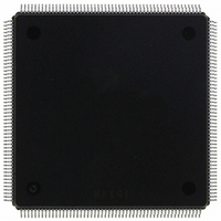
MCF5407AI220 Freescale Semiconductor, MCF5407AI220 Datasheet - Page 253

MCF5407AI220
Manufacturer Part Number
MCF5407AI220
Description
IC MPU 32B 220MHZ COLDF 208-FQFP
Manufacturer
Freescale Semiconductor
Series
MCF540xr
Specifications of MCF5407AI220
Core Processor
Coldfire V4
Core Size
32-Bit
Speed
220MHz
Connectivity
EBI/EMI, I²C, UART/USART
Peripherals
DMA, WDT
Number Of I /o
16
Program Memory Type
ROMless
Ram Size
4K x 8
Voltage - Supply (vcc/vdd)
1.65 V ~ 3.6 V
Oscillator Type
External
Operating Temperature
0°C ~ 70°C
Package / Case
208-FQFP
Maximum Clock Frequency
220 MHz
Operating Supply Voltage
1.8 V, 3.3 V
Maximum Operating Temperature
+ 105 C
Mounting Style
SMD/SMT
Minimum Operating Temperature
0 C
Program Memory Size
24KB
Cpu Speed
220MHz
Embedded Interface Type
I2C, UART
Digital Ic Case Style
FQFP
No. Of Pins
208
Supply Voltage Range
3.3V
Rohs Compliant
Yes
For Use With
M5407C3 - KIT EVAL FOR MCF5407 W/ETHERNET
Lead Free Status / RoHS Status
Lead free / RoHS Compliant
Eeprom Size
-
Program Memory Size
-
Data Converters
-
Lead Free Status / Rohs Status
Lead free / RoHS Compliant
Available stocks
Company
Part Number
Manufacturer
Quantity
Price
Company:
Part Number:
MCF5407AI220
Manufacturer:
freescaie
Quantity:
6
Company:
Part Number:
MCF5407AI220
Manufacturer:
Freescale Semiconductor
Quantity:
135
Company:
Part Number:
MCF5407AI220
Manufacturer:
FREESCALE
Quantity:
1 831
Company:
Part Number:
MCF5407AI220
Manufacturer:
Freescale Semiconductor
Quantity:
10 000
- Current page: 253 of 546
- Download datasheet (7Mb)
Internal interrupts are programmed to a level and priority. Each internal interrupt has a
unique ICR. Each of the 7 interrupt levels has 5 priorities, for a total of 35 possible priority
levels, encompassing internal and external interrupts. The four external interrupt pins offer
seven possible settings at a fixed interrupt level and priority.
The IRQPAR determines these settings for external interrupt request levels. External
interrupts can be programmed to supply an autovector or execute an external interrupt
acknowledge cycle. This is described in Section 9.2.2, “Autovector Register (AVR).”
9.2.1 Interrupt Control Registers (ICR0–ICR9)
The interrupt control registers (ICR0–ICR9) provide bits for defining the interrupt level and
priority for the interrupt source assigned to the ICR, shown in Table 9-2.
Table 9-3 describes ICR fields.
7
6–5
4–2
1–0
Bits
Address
Reset
Field
R/W
AVEC
—
IL
IP
Field
AVEC
MBAR + 0x04C (ICR0); 0x04D (ICR1); 0x04E (ICR2); 0x04F (ICR3); 0x050 (ICR4); 0x051 (ICR5);
Autovector enable. Determines whether the interrupt-acknowledge cycle input (for the internal
interrupt level indicated in IL for each interrupt) requires an autovector response.
0 Interrupting source returns vector during interrupt-acknowledge cycle.
1 SIM generates autovector during interrupt acknowledge cycle.
Reserved, should be cleared.
Interrupt level. Indicates the interrupt level assigned to each interrupt input. See Table 9-4.
Interrupt priority. Indicates the interrupt priority for internal modules within the interrupt-level
assignment. See Table 9-4.
00 Lowest
01 Low
10 High
11 Highest
7
0
Figure 9-2. Interrupt Control Registers (ICR0–ICR9)
Table 9-2. Interrupt Control Registers (Continued)
6
MBAR Offset
Table 9-3. ICRn Field Descriptions
0x052 (ICR6); 0x053 (ICR7); 0x054 (ICR8); 0x055 (ICR9)
—
—
0x053
0x054
0x055
Chapter 9. Interrupt Controller
5
Register
ICR7
ICR8
ICR9
4
DMA1
DMA2
DMA3
Description
R/W
0_00
IL
3
Name
Interrupt Controller Registers
2
1
00
IP
0
9-3
Related parts for MCF5407AI220
Image
Part Number
Description
Manufacturer
Datasheet
Request
R
Part Number:
Description:
Mcf5407 Coldfire Integrated Microprocessor User
Manufacturer:
Freescale Semiconductor, Inc
Datasheet:
Part Number:
Description:
Manufacturer:
Freescale Semiconductor, Inc
Datasheet:
Part Number:
Description:
Manufacturer:
Freescale Semiconductor, Inc
Datasheet:
Part Number:
Description:
Manufacturer:
Freescale Semiconductor, Inc
Datasheet:
Part Number:
Description:
Manufacturer:
Freescale Semiconductor, Inc
Datasheet:
Part Number:
Description:
Manufacturer:
Freescale Semiconductor, Inc
Datasheet:
Part Number:
Description:
Manufacturer:
Freescale Semiconductor, Inc
Datasheet:
Part Number:
Description:
Manufacturer:
Freescale Semiconductor, Inc
Datasheet:
Part Number:
Description:
Manufacturer:
Freescale Semiconductor, Inc
Datasheet:
Part Number:
Description:
Manufacturer:
Freescale Semiconductor, Inc
Datasheet:
Part Number:
Description:
Manufacturer:
Freescale Semiconductor, Inc
Datasheet:
Part Number:
Description:
Manufacturer:
Freescale Semiconductor, Inc
Datasheet:
Part Number:
Description:
Manufacturer:
Freescale Semiconductor, Inc
Datasheet:
Part Number:
Description:
Manufacturer:
Freescale Semiconductor, Inc
Datasheet:
Part Number:
Description:
Manufacturer:
Freescale Semiconductor, Inc
Datasheet:


