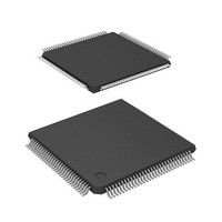
DF2398TE20 Renesas Electronics America, DF2398TE20 Datasheet - Page 23

DF2398TE20
Manufacturer Part Number
DF2398TE20
Description
IC H8S MCU FLASH 256K 120TQFP
Manufacturer
Renesas Electronics America
Series
H8® H8S/2300r
Specifications of DF2398TE20
Core Processor
H8S/2000
Core Size
16-Bit
Speed
20MHz
Connectivity
SCI, SmartCard
Peripherals
DMA, POR, PWM, WDT
Number Of I /o
87
Program Memory Size
256KB (256K x 8)
Program Memory Type
FLASH
Ram Size
8K x 8
Voltage - Supply (vcc/vdd)
4.5 V ~ 5.5 V
Data Converters
A/D 8x10b; D/A 2x8b
Oscillator Type
Internal
Operating Temperature
-20°C ~ 75°C
Package / Case
120-TQFP, 120-VQFP
Lead Free Status / RoHS Status
Contains lead / RoHS non-compliant
Eeprom Size
-
Other names
HD64F2398TE20
HD64F2398TE20
HD64F2398TE20
Available stocks
Company
Part Number
Manufacturer
Quantity
Price
Company:
Part Number:
DF2398TE20V
Manufacturer:
Renesas Electronics America
Quantity:
10 000
- Current page: 23 of 1049
- Download datasheet (5Mb)
Section 13 Watchdog Timer .............................................................................................................453
13.1 Overview................................................................................................................................................................... 453
13.2 Register Descriptions................................................................................................................................................456
13.3 Operation ..................................................................................................................................................................460
13.4 Interrupts................................................................................................................................................................... 462
13.5 Usage Notes ..............................................................................................................................................................463
Section 14 Serial Communication Interface (SCI) ...........................................................................465
14.1 Overview................................................................................................................................................................... 465
14.2 Register Descriptions................................................................................................................................................469
14.3 Operation ..................................................................................................................................................................487
12.6.2 Contention between TCNT Write and Increment ....................................................................................... 449
12.6.3 Contention between TCOR Write and Compare Match ............................................................................. 450
12.6.4 Contention between Compare Matches A and B ........................................................................................450
12.6.5 Switching of Internal Clocks and TCNT Operation................................................................................... 451
12.6.6 Interrupts and Module Stop Mode............................................................................................................... 452
13.1.1 Features ....................................................................................................................................................... 453
13.1.2 Block Diagram............................................................................................................................................. 454
13.1.3 Pin Configuration ........................................................................................................................................454
13.1.4 Register Configuration ................................................................................................................................455
13.2.1 Timer Counter (TCNT) ............................................................................................................................... 456
13.2.2 Timer Control/Status Register (TCSR) ....................................................................................................... 456
13.2.3 Reset Control/Status Register (RSTCSR) ................................................................................................... 457
13.2.4 Notes on Register Access ............................................................................................................................459
13.3.1 Watchdog Timer Operation......................................................................................................................... 460
13.3.2 Interval Timer Operation............................................................................................................................. 461
13.3.3 Timing of Setting Overflow Flag (OVF)..................................................................................................... 461
13.3.4 Timing of Setting of Watchdog Timer Overflow Flag (WOVF) ................................................................462
13.5.1 Contention between Timer Counter (TCNT) Write and Increment ............................................................463
13.5.2 Changing Value of CKS2 to CKS0............................................................................................................. 463
13.5.3 Switching between Watchdog Timer Mode and Interval Timer Mode....................................................... 463
13.5.4 System Reset by WDTOVF Signal ............................................................................................................. 463
13.5.5 Internal Reset in Watchdog Timer Mode ....................................................................................................464
14.1.1 Features ....................................................................................................................................................... 465
14.1.2 Block Diagram............................................................................................................................................. 467
14.1.3 Pin Configuration ........................................................................................................................................467
14.1.4 Register Configuration ................................................................................................................................468
14.2.1 Receive Shift Register (RSR)......................................................................................................................469
14.2.2 Receive Data Register (RDR) ..................................................................................................................... 469
14.2.3 Transmit Shift Register (TSR)..................................................................................................................... 469
14.2.4 Transmit Data Register (TDR) ....................................................................................................................470
14.2.5 Serial Mode Register (SMR)....................................................................................................................... 470
14.2.6 Serial Control Register (SCR)..................................................................................................................... 472
14.2.7 Serial Status Register (SSR)........................................................................................................................475
14.2.8 Bit Rate Register (BRR)..............................................................................................................................478
14.2.9 Smart Card Mode Register (SCMR) ........................................................................................................... 485
14.2.10 Module Stop Control Register (MSTPCR) ................................................................................................. 486
14.3.1 Overview ..................................................................................................................................................... 487
14.3.2 Operation in Asynchronous Mode............................................................................................................... 489
14.3.3 Multiprocessor Communication Function................................................................................................... 499
14.3.4 Operation in Clocked Synchronous Mode ..................................................................................................505
Rev.6.00 Oct.28.2004 page xvii of xxiv
REJ09B0138-0600H
Related parts for DF2398TE20
Image
Part Number
Description
Manufacturer
Datasheet
Request
R

Part Number:
Description:
CONN PLUG 12POS DUAL 0.5MM SMD
Manufacturer:
Hirose Electric Co Ltd
Datasheet:

Part Number:
Description:
CONN PLUG 18POS DUAL 0.5MM SMD
Manufacturer:
Hirose Electric Co Ltd
Datasheet:

Part Number:
Description:
CONN PLUG 14POS DUAL 0.5MM SMD
Manufacturer:
Hirose Electric Co Ltd
Datasheet:

Part Number:
Description:
CONN RECEPT 20POS DUAL 0.5MM SMD
Manufacturer:
Hirose Electric Co Ltd
Datasheet:

Part Number:
Description:
CONN PLUG 16POS DUAL 0.5MM SMD
Manufacturer:
Hirose Electric Co Ltd
Datasheet:

Part Number:
Description:
CONN RECEPT 16POS DUAL 0.5MM SMD
Manufacturer:
Hirose Electric Co Ltd
Datasheet:

Part Number:
Description:
CONN PLUG 20POS DUAL 0.5MM SMD
Manufacturer:
Hirose Electric Co Ltd
Datasheet:

Part Number:
Description:
CONN PLUG 30POS DUAL 0.5MM SMD
Manufacturer:
Hirose Electric Co Ltd
Datasheet:

Part Number:
Description:
CONN RECEPT 30POS DUAL 0.5MM SMD
Manufacturer:
Hirose Electric Co Ltd
Datasheet:

Part Number:
Description:
CONN PLUG 40POS DUAL 0.5MM SMD
Manufacturer:
Hirose Electric Co Ltd
Datasheet:

Part Number:
Description:
KIT STARTER FOR M16C/29
Manufacturer:
Renesas Electronics America
Datasheet:

Part Number:
Description:
KIT STARTER FOR R8C/2D
Manufacturer:
Renesas Electronics America
Datasheet:

Part Number:
Description:
R0K33062P STARTER KIT
Manufacturer:
Renesas Electronics America
Datasheet:

Part Number:
Description:
KIT STARTER FOR R8C/23 E8A
Manufacturer:
Renesas Electronics America
Datasheet:

Part Number:
Description:
KIT STARTER FOR R8C/25
Manufacturer:
Renesas Electronics America
Datasheet:


