R8A77850ADBGV#RD0Z Renesas Electronics America, R8A77850ADBGV#RD0Z Datasheet - Page 1049
R8A77850ADBGV#RD0Z
Manufacturer Part Number
R8A77850ADBGV#RD0Z
Description
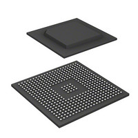
IC SUPERH MPU ROMLESS 436-BGA
Manufacturer
Renesas Electronics America
Series
SuperH® SH7780r
Datasheet
1.R8A77850AADBGV.pdf
(1694 pages)
Specifications of R8A77850ADBGV#RD0Z
Core Processor
SH-4A
Core Size
32-Bit
Speed
600MHz
Connectivity
Audio Codec, MMC, Serial Sound, SCI, SIO, SPI, SSI
Peripherals
DMA, POR, WDT
Number Of I /o
108
Program Memory Type
ROMless
Ram Size
8K x 8
Voltage - Supply (vcc/vdd)
1 V ~ 1.2 V
Oscillator Type
External
Operating Temperature
-40°C ~ 85°C
Package / Case
436-BGA
Lead Free Status / RoHS Status
Lead free / RoHS Compliant
Eeprom Size
-
Program Memory Size
-
Data Converters
-
Available stocks
Company
Part Number
Manufacturer
Quantity
Price

Part Number:
R8A77850ADBGV#RD0ZR8A77850ADBGV
Manufacturer:
Renesas Electronics America
Quantity:
10 000


(3)
Various initial settings are made by the CPU, and processing is started. The processing procedure
is the same for YUYV conversion mode and for ARGB conversion mode, except that in ARGB
conversion mode the data of the color conversion table must be prepared in buffer RAM 0. The
procedure is described below.
No. Operation
(4) ARGB
(5) Output data
conversion
writing
CL Processing Procedure
Description
ARGB data is generated from color information read from buffer RAM 0
using the following formula, and the converted data is output in the format
shown in the display image of figure 20.4. ARGB conversion is performed
according to the following conversion logic.
A = The result of computation of clip_0_255((A+16)>> 5) for unsigned 16-bit
data (11 integer bits, 5 decimal bits) read from RAM 0 is output.
R = clip_0_255((Y1 +
G = clip_0_255((Y1 + U0 + V1 + 16) >> 5);
B = clip_0_255((Y1 + U1
When Y1 = 0, the conversion result is R, G, B = 0.
clip_0_255: 8-bit saturation calculation (0 ≤ x ≤ 255) (the sign is determined
by the uppermost bit (bit 15))
The converted data is output according to the conversion data output order
in the display image of figure 20.4, regardless of the output destination.
Converted data is output by the size 4 x the frame width specified by
CLWR, rounded up to an integral multiple of 32 bytes.
Because output data is transferred in 32 byte units, one line of output data,
including output padding, should be made an integral multiple of 32 bytes.
Padding data other than that used for adjustment for the 32-byte boundary
is not output.
The output data write address for the next line output is calculated by
adding, to the current write address, the size of the padding data that is
specified as the output padding size for each line.
V0 + 16) >> 5);
20. Graphics Data Translation Accelerator (GDTA)
+ 16) >> 5);
Rev.1.00 Jan. 10, 2008 Page 1017 of 1658
REJ09B0261-0100
Related parts for R8A77850ADBGV#RD0Z
Image
Part Number
Description
Manufacturer
Datasheet
Request
R

Part Number:
Description:
KIT STARTER FOR M16C/29
Manufacturer:
Renesas Electronics America
Datasheet:

Part Number:
Description:
KIT STARTER FOR R8C/2D
Manufacturer:
Renesas Electronics America
Datasheet:

Part Number:
Description:
R0K33062P STARTER KIT
Manufacturer:
Renesas Electronics America
Datasheet:

Part Number:
Description:
KIT STARTER FOR R8C/23 E8A
Manufacturer:
Renesas Electronics America
Datasheet:

Part Number:
Description:
KIT STARTER FOR R8C/25
Manufacturer:
Renesas Electronics America
Datasheet:

Part Number:
Description:
KIT STARTER H8S2456 SHARPE DSPLY
Manufacturer:
Renesas Electronics America
Datasheet:

Part Number:
Description:
KIT STARTER FOR R8C38C
Manufacturer:
Renesas Electronics America
Datasheet:

Part Number:
Description:
KIT STARTER FOR R8C35C
Manufacturer:
Renesas Electronics America
Datasheet:

Part Number:
Description:
KIT STARTER FOR R8CL3AC+LCD APPS
Manufacturer:
Renesas Electronics America
Datasheet:
Part Number:
Description:
KIT STARTER FOR RX610
Manufacturer:
Renesas Electronics America
Datasheet:

Part Number:
Description:
KIT STARTER FOR R32C/118
Manufacturer:
Renesas Electronics America
Datasheet:

Part Number:
Description:
KIT DEV RSK-R8C/26-29
Manufacturer:
Renesas Electronics America
Datasheet:

Part Number:
Description:
KIT STARTER FOR SH7124
Manufacturer:
Renesas Electronics America
Datasheet:

Part Number:
Description:
KIT STARTER FOR H8SX/1622
Manufacturer:
Renesas Electronics America
Datasheet:

Part Number:
Description:
KIT DEV FOR SH7203
Manufacturer:
Renesas Electronics America
Datasheet: