R8A77850ADBGV#RD0Z Renesas Electronics America, R8A77850ADBGV#RD0Z Datasheet - Page 974
R8A77850ADBGV#RD0Z
Manufacturer Part Number
R8A77850ADBGV#RD0Z
Description
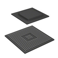
IC SUPERH MPU ROMLESS 436-BGA
Manufacturer
Renesas Electronics America
Series
SuperH® SH7780r
Datasheet
1.R8A77850AADBGV.pdf
(1694 pages)
Specifications of R8A77850ADBGV#RD0Z
Core Processor
SH-4A
Core Size
32-Bit
Speed
600MHz
Connectivity
Audio Codec, MMC, Serial Sound, SCI, SIO, SPI, SSI
Peripherals
DMA, POR, WDT
Number Of I /o
108
Program Memory Type
ROMless
Ram Size
8K x 8
Voltage - Supply (vcc/vdd)
1 V ~ 1.2 V
Oscillator Type
External
Operating Temperature
-40°C ~ 85°C
Package / Case
436-BGA
Lead Free Status / RoHS Status
Lead free / RoHS Compliant
Eeprom Size
-
Program Memory Size
-
Data Converters
-
Available stocks
Company
Part Number
Manufacturer
Quantity
Price

Part Number:
R8A77850ADBGV#RD0ZR8A77850ADBGV
Manufacturer:
Renesas Electronics America
Quantity:
10 000


19. Display Unit (DU)
19.4.8
8 bits/pixel data employs color palettes. Four color palettes can be used; these are called color
palette 1, color palette 2, color palette 3, and color palette 4.
The color palette used in each plane can be set to any among color palette 1, color palette 2, color
palette 3, and color palette 4 using the PnCPSL bits in PnMR. Each of the color palettes consists
of two alternate buffers; one serves as a display buffer, and the other is for CPU access. After
setting each color palette, by setting the color palette switching enable bits (CP4CE, CP3CE,
CP2CE, CP1CE) in CPCR to 1, the color palette thus set becomes valid at the next VSYNC falling
edge (internal update timing), or upon display reset (when the DRES bit in DSYSR is changed
from 1 to 0).
Notes on Use of Color Palettes:
1. Because palettes consist of alternate buffers, complete overwriting is necessary upon a color
2. Upon completion of color palette settings, the switching enable bit must always be set to 1.
3. When reading a color palette which has been written from the CPU, reading should be
Procedure For Setting A Color Palette:
• Procedure for switching from the initial state
• Procedure for switching from display state
Rev.1.00 Jan. 10, 2008 Page 942 of 1658
REJ09B0261-0100
palette update. However, when the details of color palette updates are being managed, there is
no problem with overwriting only the relevant part.
performed before setting the switching enabled bit to 1. If read after setting the bit to 1, there is
the possibility that different palette contents may be read after palette switching occurs.
The initial state (after power-on reset) is the display reset state.
A. Set the registers of the display unit (DU).
B. Set either color palette 1, color palette 2, color palette 3, or color palette 4.
C. After setting the color palette, set the color palette switching enable bit to 1.
D. Cancel the display reset.
In the display state, the DRES bit and DEN bit in the DSYSR are 0 and 1 respectively.
A. Confirm that the color palette switching enable bit is 0.
B. Set either color palette 1, color palette 2, color palette 3, or color palette 4.
C. After setting the color palette, set the color palette switching enable bit to 1.
Color Palettes
Related parts for R8A77850ADBGV#RD0Z
Image
Part Number
Description
Manufacturer
Datasheet
Request
R

Part Number:
Description:
KIT STARTER FOR M16C/29
Manufacturer:
Renesas Electronics America
Datasheet:

Part Number:
Description:
KIT STARTER FOR R8C/2D
Manufacturer:
Renesas Electronics America
Datasheet:

Part Number:
Description:
R0K33062P STARTER KIT
Manufacturer:
Renesas Electronics America
Datasheet:

Part Number:
Description:
KIT STARTER FOR R8C/23 E8A
Manufacturer:
Renesas Electronics America
Datasheet:

Part Number:
Description:
KIT STARTER FOR R8C/25
Manufacturer:
Renesas Electronics America
Datasheet:

Part Number:
Description:
KIT STARTER H8S2456 SHARPE DSPLY
Manufacturer:
Renesas Electronics America
Datasheet:

Part Number:
Description:
KIT STARTER FOR R8C38C
Manufacturer:
Renesas Electronics America
Datasheet:

Part Number:
Description:
KIT STARTER FOR R8C35C
Manufacturer:
Renesas Electronics America
Datasheet:

Part Number:
Description:
KIT STARTER FOR R8CL3AC+LCD APPS
Manufacturer:
Renesas Electronics America
Datasheet:
Part Number:
Description:
KIT STARTER FOR RX610
Manufacturer:
Renesas Electronics America
Datasheet:

Part Number:
Description:
KIT STARTER FOR R32C/118
Manufacturer:
Renesas Electronics America
Datasheet:

Part Number:
Description:
KIT DEV RSK-R8C/26-29
Manufacturer:
Renesas Electronics America
Datasheet:

Part Number:
Description:
KIT STARTER FOR SH7124
Manufacturer:
Renesas Electronics America
Datasheet:

Part Number:
Description:
KIT STARTER FOR H8SX/1622
Manufacturer:
Renesas Electronics America
Datasheet:

Part Number:
Description:
KIT DEV FOR SH7203
Manufacturer:
Renesas Electronics America
Datasheet: